Rugged fiber optic towed array

a technology of towed arrays and fiber optics, applied in the direction of optical elements, instruments, using wave/particle radiation means, etc., can solve the problems of high production costs, poor reliability during handling operations, and high manufacturing equipment requirements for rigid mandrels and flexible links, etc., to achieve excellent acoustic properties and sensitivity, the effect of being easy to break

Inactive Publication Date: 2009-09-03
SABEUS
View PDF7 Cites 8 Cited by
  • Summary
  • Abstract
  • Description
  • Claims
  • Application Information

AI Technical Summary

Benefits of technology

[0005]The present invention provides a rugged fiber optic towed array suitable for use in harsh environments, such as below the surface of a body of water. In various aspects, arrays in accordance with the principles of the present invention provide a rugged towed array that is relatively inexpensive to produce, yet which provides an array that is resistant to breakage while being towed, resistant to crushing or other damage during spooling while being deployed or retrieved, yet provides for excellent acoustic properties and sensitivity.
[0009]In a still further aspect, the mandrel may include helixed sections located at desired periodicity along the mandrel to provide attenuation and isolation of longitudinal vibrations which might otherwise propagate along the array increasing the acoustic self noise of the array. The helixed sections also provide for transverse flexibility in the array when it is spooled. The helixed sections may also be grooved to allow for a protected, uniform and continuous distribution of the optical along the mandrel.

Problems solved by technology

Winding the optical fiber at a very closely controlled tension and pitch, while at the same time applying adhesive, over rigid mandrels and flexible links requires expensive and precise manufacturing equipment.
Two significant problems are associated with the current state-of-the-art fiber optic towed arrays.
They are expensive to produce due to the high level of manual labor needed to fabricate the sensors and assemble the arrays.
They also suffer from reliability during handling operations.
Failures of the optical fibers within the array are caused by fiber abrasion and microbending at rigid-flexible structure interfaces and by crushing when exposed to radial compression while wound on a handling reel.

Method used


Image

  • Rugged fiber optic towed array
  • Rugged fiber optic towed array
  • Rugged fiber optic towed array

Examples


Embodiment Construction

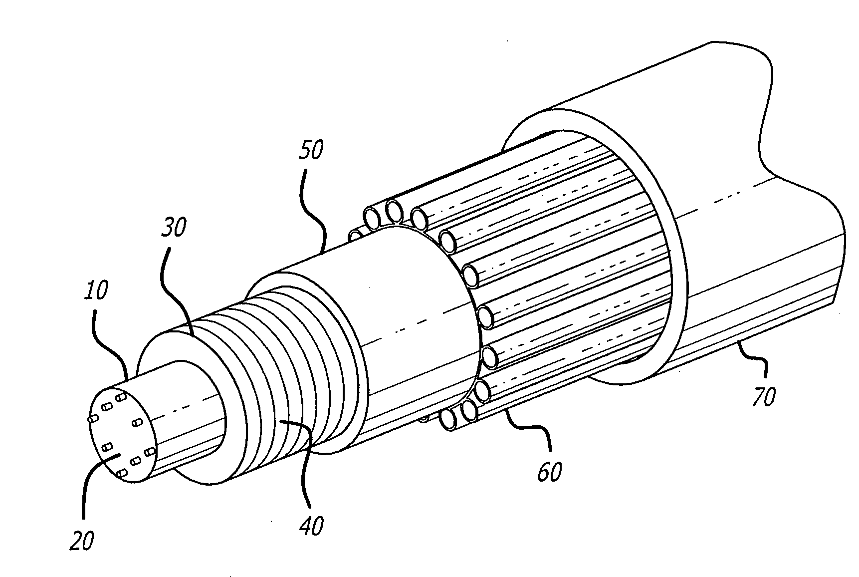
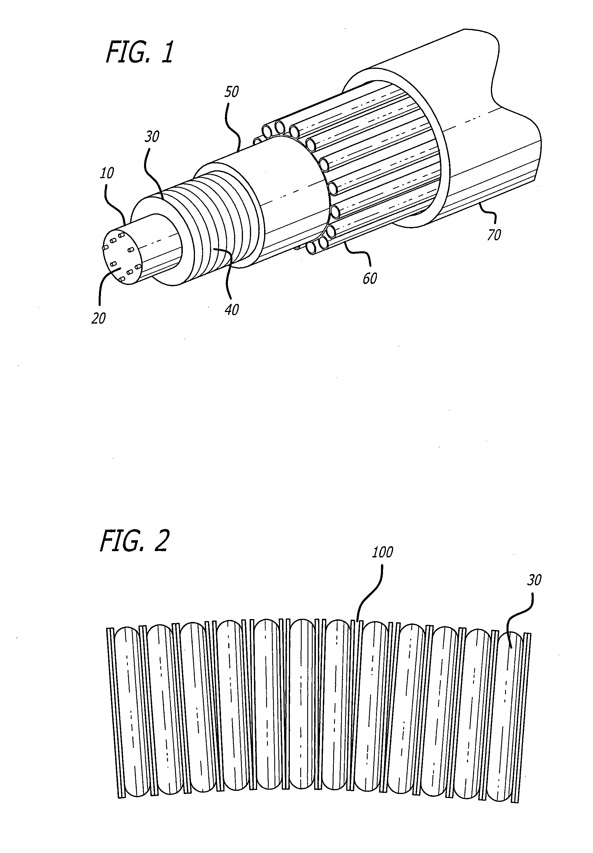
[0019]While several particular forms of the invention have been illustrated and described, it will be apparent that various modifications can be made without departing from the spirit and scope of the invention. In a preferred embodiment, as depicted in the exemplary drawing of FIG. 1, the construction includes a central flexible core 10, within which pass-through fibers 20. Through fibers are defined as fibers that are not used for sensing in a given acoustic module, and are either helically wound within the flexible core or passed through the center of the flexible core. Fiber Bragg Grating (FBG) arrays (not shown) can also be helically wound within the core for measuring the shape of the array. The core is constructed with the fiber wound around a core layer of voided plastic, such as polyurethane or other appropriate polymers, then overcoated with the same material for protection. Use of the voided plastic helps to ensure neutral buoyancy of the array, while avoiding the use of ...


PUM


Abstract

A fiber optic towed array is provided. The array includes a flexible core upon which is disposed a semi-rigid mandrel. The semi-rigid mandrel has a helical groove formed therein, in which is disposed an optical fiber, the optical fiber including a plurality of fiber gratings. The mandrel is in turn covered with a nylon or fiber screen and encased in a layer of open cell foam, which is encased in a protective covering that includes at least one strength member disposed along a longitudinal axis of the array.

Description

BACKGROUND OF THE INVENTION[0001]Fiber optic towed arrays are commonly constructed of a series of sensors interconnected along and within a common hose or casing. The sensors are typically comprised of buffered (with thin, approximately 40-50 micron thick plastic coating) optical fiber precision wound with adhesives on concentric, rigid tubes or mandrels. In some cases, the outer tubes are surrounded by rigid, perforated, cylindrical ‘cages’.[0002]The mandrels upon which the fiber is wound are typically rigid with an air backing to allow sufficient compliance of the structure so that the fiber can respond to applied acoustic pressure signals, yet not collapse at operating water depths. Since the completed towed array must be reeled onto a drum for storage, it must be relatively flexible. This requirement for flexibility limits the length of the individual rigid mandrels to not more than a few inches, thus a flexible link between the hundreds of rigid mandrels is required. The optica...

Claims


Application Information

Patent Timeline
Patent Type & Authority Applications(United States)
IPC IPC(8): G02B6/00
CPCG01V1/208G01H9/004
Inventor GOLDNER, ERIC LEEDEMETZ, FRED
Owner SABEUS
Why Eureka
Try Eureka