Digital bio disc (dbd), dbd driver apparatus, and assay method using the same

a technology of driver apparatus and bio disc, which is applied in the field of digital bio disc, can solve the problems of poor sensitivity problem of light receiving unit, high cost of analyzer, poor sensitivity of centralized laboratories and hospitals, etc., and achieve the effects of increasing the surface area of the assay site, increasing sensitivity, and being harmless to the human body

Inactive Publication Date: 2009-09-03
SAMSUNG ELECTRONICS CO LTD
View PDF5 Cites 36 Cited by
  • Summary
  • Abstract
  • Description
  • Claims
  • Application Information

AI Technical Summary

Benefits of technology

[0050]In the DBD according to an aspect of the embodiment, the porous membrane may be any membrane having a large number of pores. Preferably, the porous membrane may be one selected from a group consisting a NC (nitrocellose) membrane, a nylon membrane, and aligned nanotubes. Due to the porous membrane according to the present invention, a surface area of the assay site can be increased, so that a large amount of bio material can be combined. Accordingly, it is possible to increase sensitivity.
[0051]In the DBD according to an aspect of the embodiment, the hydrophilic channel may be any channel where a hydrophilic material exists on a surface thereof. Preferably, the hydrophilic channel may be constructed by coating a surface of a hydrophobic channel with a hydrophilic acrylate, an ultra-hydrophilic poly (N-isopropylacrylamide) (PI...

Problems solved by technology

However, these analyzers are expensive and only centralized laboratories and hospitals can afford them.
Such centralization necessitates sample transport to the laboratory or hospital and often precludes urgent or emergent analysis of time-critical samples.
In this structure, its optical traveling path is relatively long, and there is a poor sensitivity problem of the light receiving unit.
Furthermore, when such an optical disc read by laser scanning is applied to a bio-assay device, problems such as physical deformation of probes and inaccurate assay results occur.
Therefore, it is impossible for a general optical pickup (CD or DVD reader) to read a bio-disc, which makes a new pickup device needed.
However, the above-listed conventional assay devices failed to ensure perfect automation in assay and diagnosis and are unsuitable for a lab-on-a-chip.
The conventional ...

Method used


Image

  • Digital bio disc (dbd), dbd driver apparatus, and assay method using the same
  • Digital bio disc (dbd), dbd driver apparatus, and assay method using the same
  • Digital bio disc (dbd), dbd driver apparatus, and assay method using the same

Examples


Embodiment Construction

[0150]Reference will now be made in detail to the embodiments, examples of which are illustrated in the accompanying drawings, wherein like reference numerals refer to the like elements throughout. The embodiments are described below to explain an aspect of embodiment by referring to the figures.

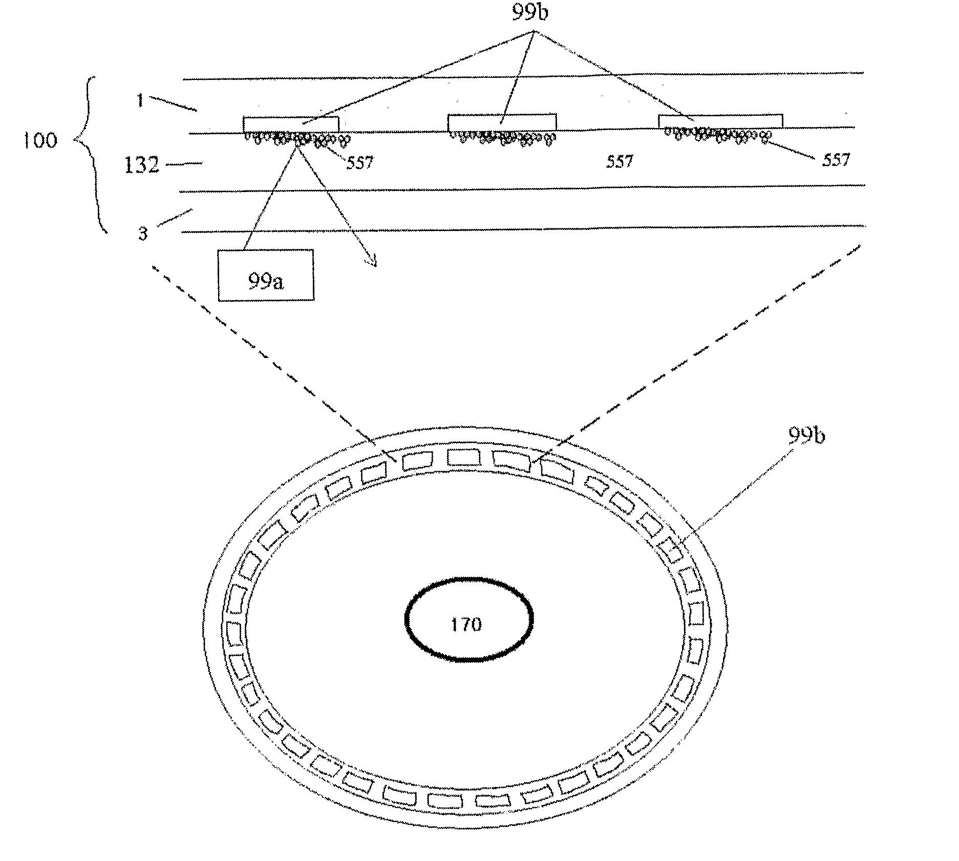
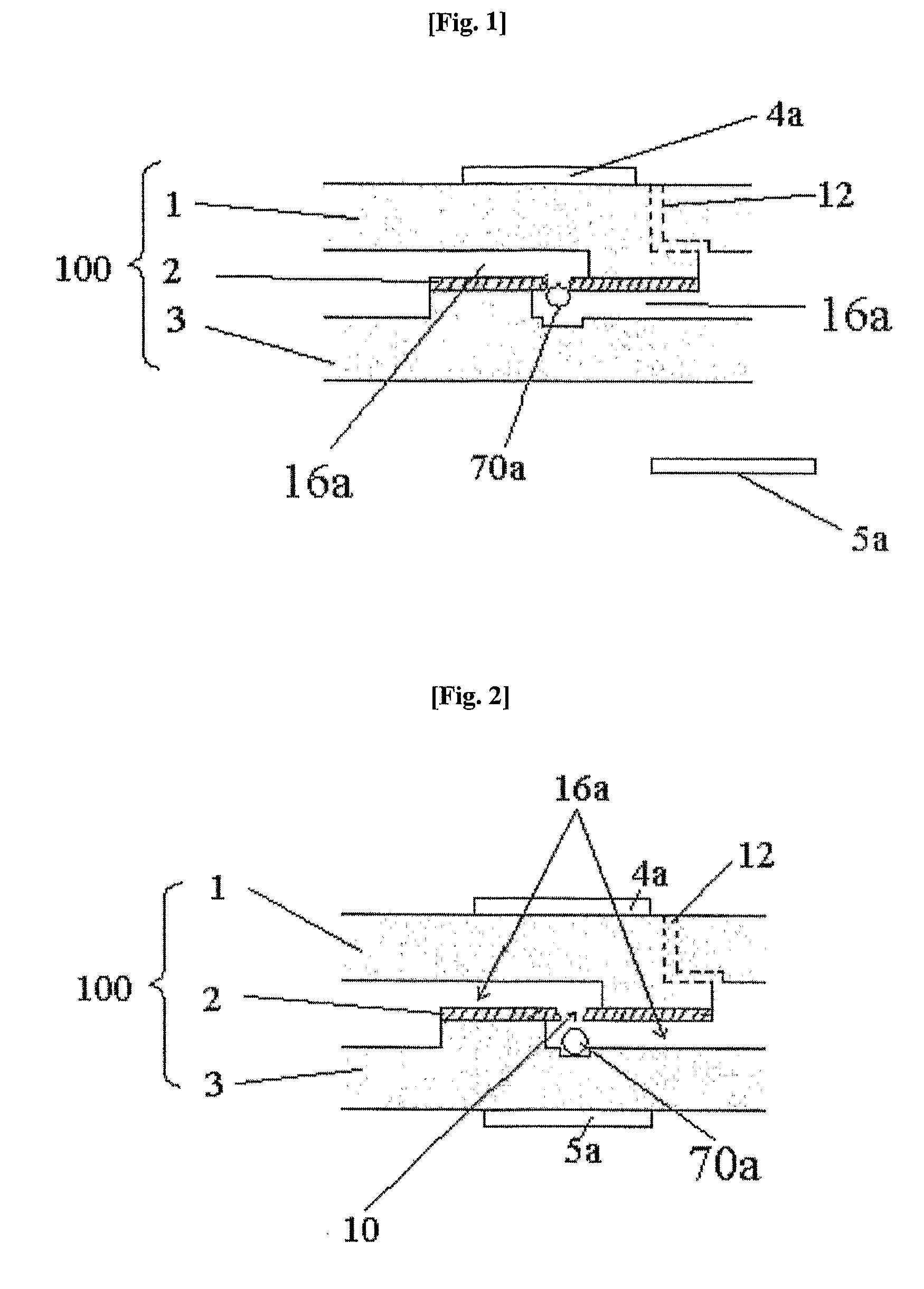
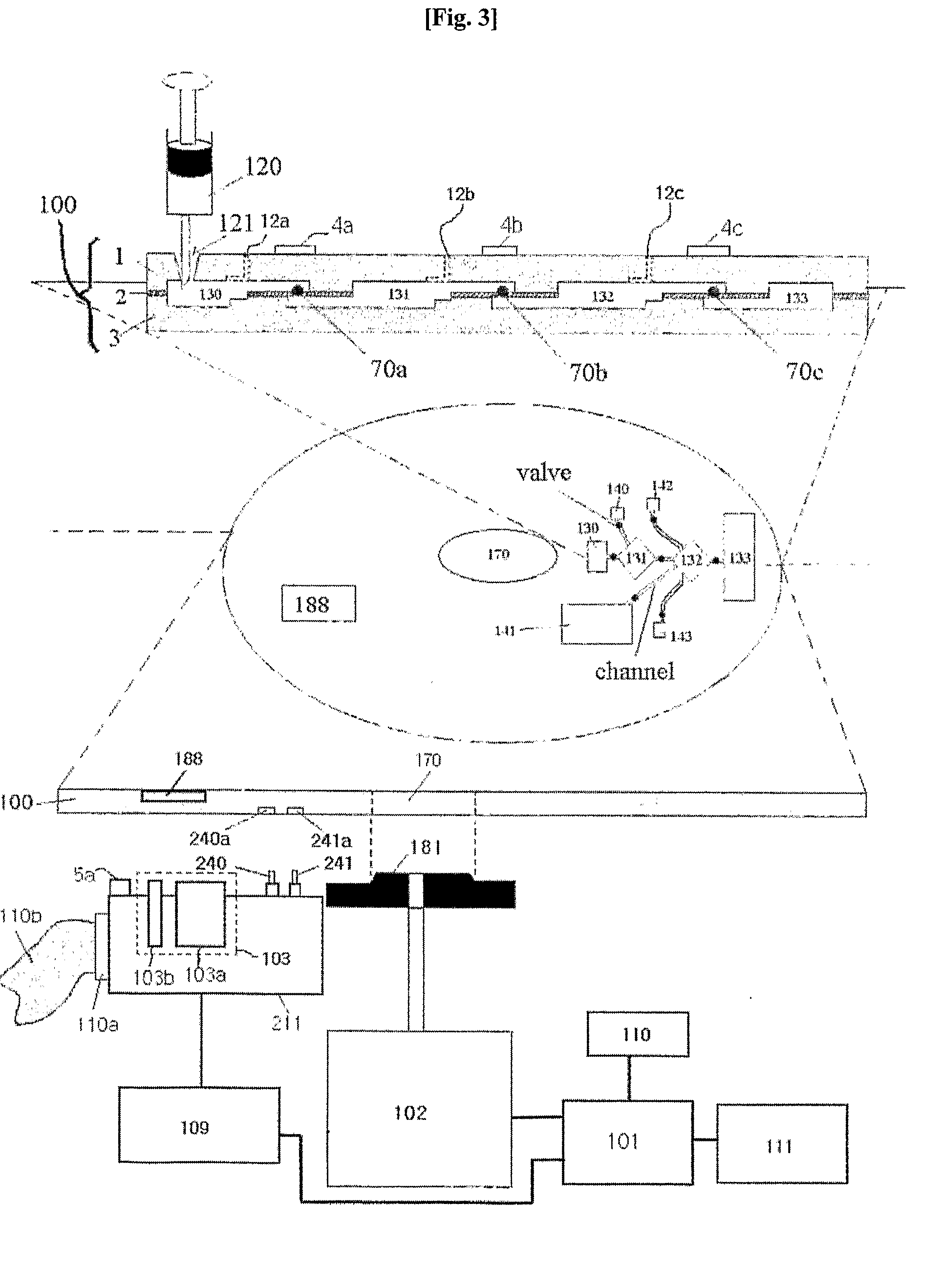
[0151]A DBD according to an aspect of embodiment includes a valve which controls fluid flow or the flow rate in a lab-on-a-chip integrated in the DBD. The valve opens or closes a channel formed in the DBD using a microbead that is movable by the magnetic force generated by a permanent magnet and a movable permanent magnet disposed on the top and bottom surface of the DBD. International Patent Application No. PCT / KR02 / 01035 filed 31 May 2002 and its priority Korean Application No. 10-2001-0031284 filed 31 May 2002, which are entitled “Micro valve apparatus using microbead and method for controlling the same”, can be referred to for the detailed structure of the valve.

[0152]In exemplary embodi...


PUM

PropertyMeasurementUnit
Wavelengthaaaaaaaaaa
Temperatureaaaaaaaaaa

Abstract

An aspect of embodiment relates to a digital bio disc (DBD) including new valve control means and fluid movement system, a digital bio disc (DBD) driver apparatus, and an assay method using the same. More particularly, an aspect of embodiment relates to a DBD with a lab-on-a-chip for various diagnostic assays, nucleic acid hybridization assays, or immunoassays, a DBD driver apparatus integrated with a controller for controlling the DBD and a general optical disc (CD or DVD), and an assay method using the same.

Description

CROSS-REFERENCE TO RELATED APPLICATIONS[0001]This application claims the benefit of PCT Application No. PCT / KR2006 / 001709, filed May 6, 2006, and Korean Application No. 10-2005-0038765, filed May 6, 2005 in the Korean Intellectual Property Office, the disclosures of which is incorporated herein by reference.BACKGROUND[0002]1. Field[0003]One or more embodiments relates to a digital bio disc (DBD) including new valve control means and fluid movement system, a digital bio disc (DBD) driver apparatus, and an assay method using the same. More particularly, the present invention relates to a DBD with a lab-on-a-chip for various diagnostic assays, nucleic acid hybridization assays, or immunoassays, a DBD driver apparatus integrated with a controller for controlling the DBD and a general optical disc (CD or DVD), and an assay method using the same.[0004]Hereafter, a digital bio disc and a digital bio disc driver apparatus are referred to as a “DBD” and a “DBD driver apparatus”, respectively...

Claims


Application Information

Patent Timeline
IPC IPC(8): C40B30/04C40B60/12
CPCB01J2219/00536G01N35/00069B01J2219/00605B01J2219/0061B01J2219/00612B01J2219/00641B01J2219/00704B01L3/50273B01L3/502738B01L7/52B01L2300/022B01L2300/023B01L2300/024B01L2300/0636B01L2300/0645B01L2300/0806B01L2300/0867B01L2300/087B01L2300/0874B01L2300/0887B01L2300/1827B01L2400/0406B01L2400/0409B01L2400/0475B01L2400/0616B01L2400/0633C12Q1/6825F16K99/0001F16K99/0017F16K99/0023F16K99/0034F16K2099/0078F16K2099/0084G01N33/54386B01J2219/00596
Inventor YOO, JAE CHERN
Owner SAMSUNG ELECTRONICS CO LTD
Why Eureka
Try Eureka