
Boiler control system

a control system and boiler technology, applied in the field of control systems, can solve the problems of inefficient boiler operation, inability to account for time lag, etc., and achieve the effect of reducing “hunting”

Active Publication Date: 2009-09-10
KNORR JR WARREN G
View PDF12 Cites 16 Cited by
  • Summary
  • Abstract
  • Description
  • Claims
  • Application Information

AI Technical Summary

Benefits of technology

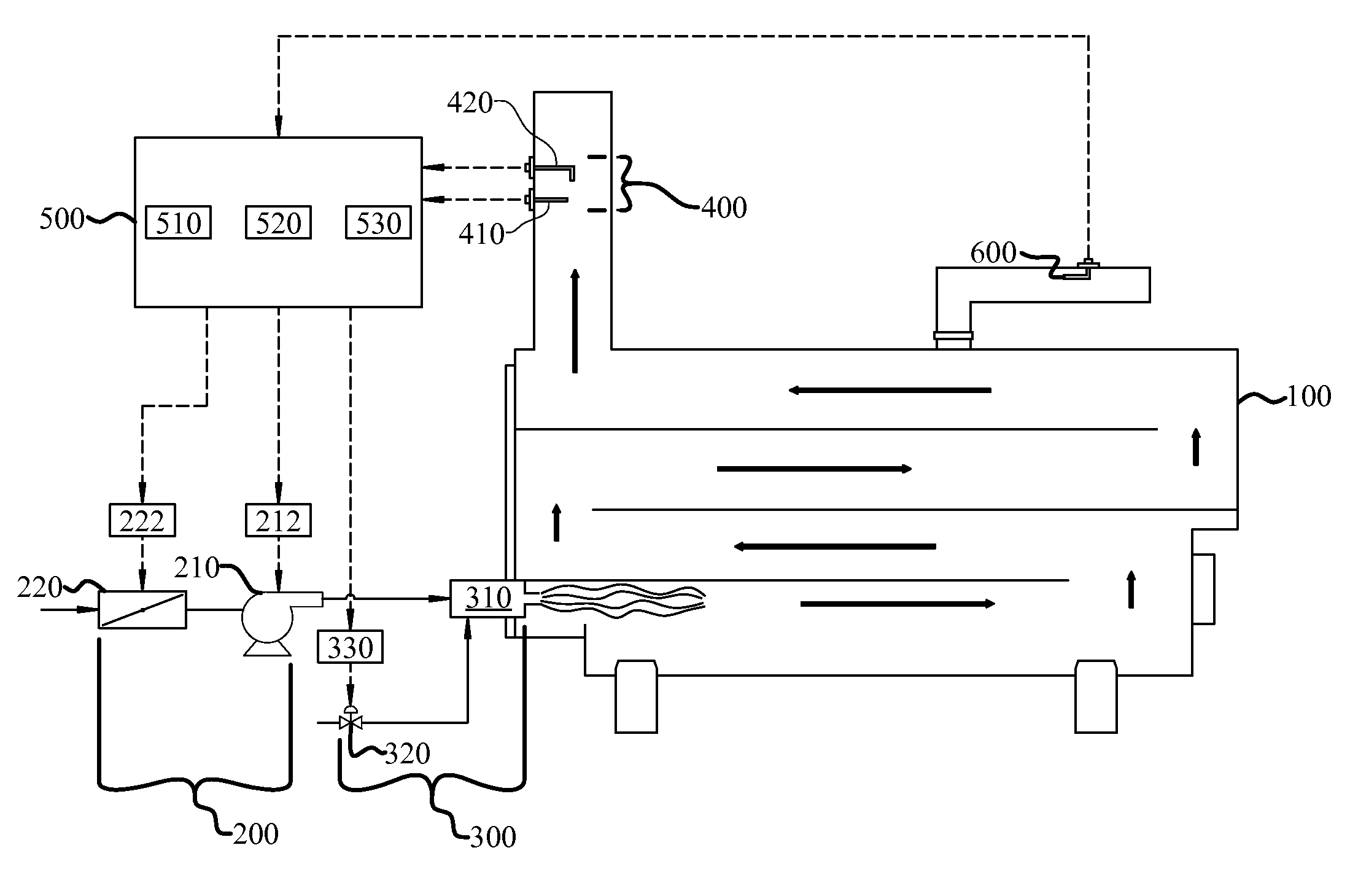
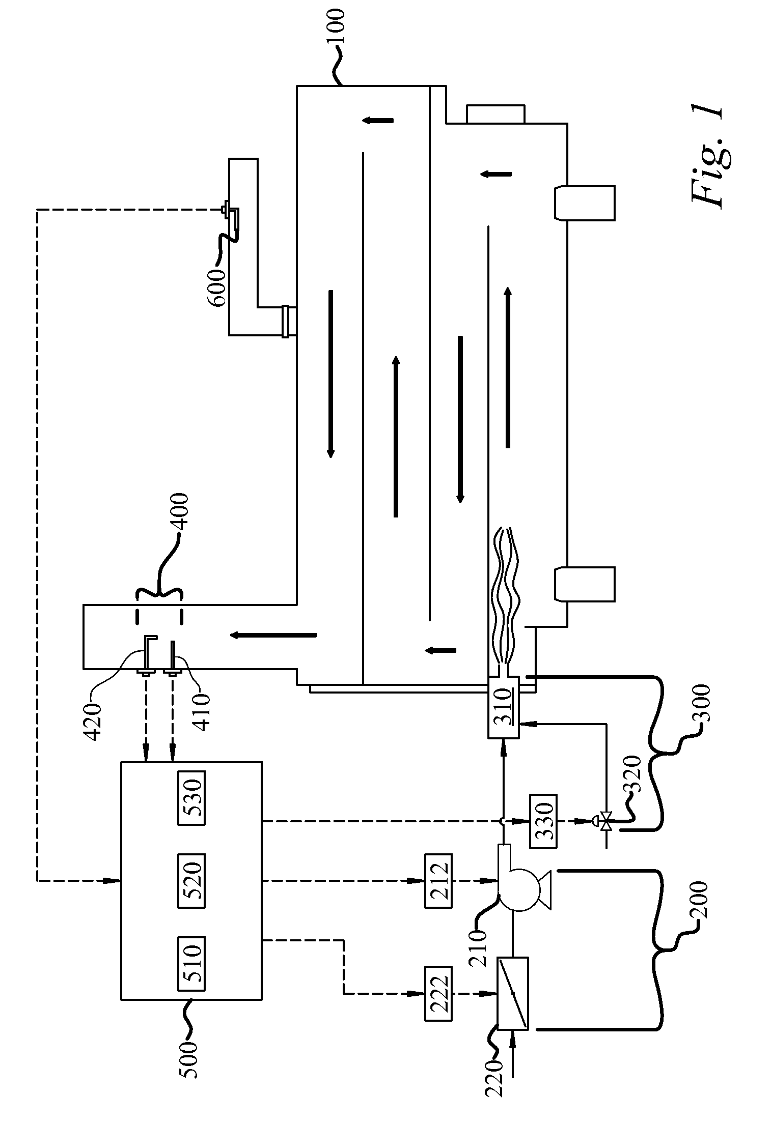
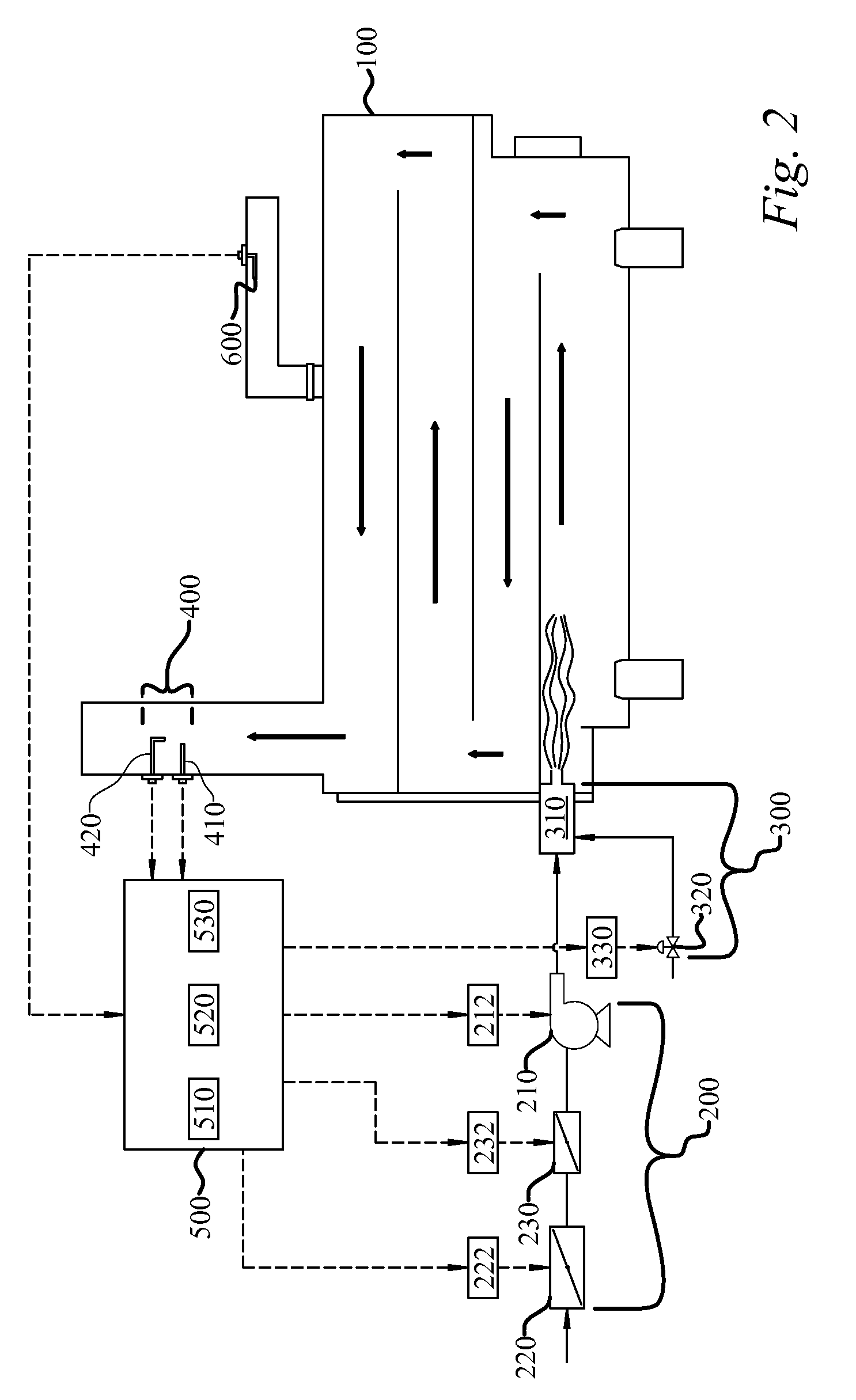
[0008]The present invention is a boiler control system for efficiently controlling the operation of a boiler. The boiler control system generally includes a combustion air control system, a fuel control system, a flue gas sensing system, and a boiler controller.
[0015]Execution of the fine-level control begins after the flue gas differential sensor has sensed a change in the predetermined characteristic that meets the flue gas differential setpoint. The fine-level control is used to optimize the efficiency of the boiler by maintaining the amount of oxygen in the flue gas at the flue gas oxygen setpoint.
[0017]The boiler control system of the instant invention addresses the time lag by controlling fine-level operation of the combustion air control system or the fuel control system only after a change in a predetermined characteristic of the flue gas has been sensed by the flue gas differential sensor. Thus, the boiler control system efficiently controls the operation of the boiler by ensuring that fine-level control of oxygen in the flue gas, or excess air, is based on the combustion conditions occurring at the burner.
[0021]Additionally, in one embodiment, the boiler controller may be programmed to control fine-level operation only when the change in a predetermined characteristic of the flue gas, as measured by the flue gas differential sensor, meets the flue gas differential setpoint and is sustained for a certain amount of time. This embodiment will help ensure that the boiler has reached some degree of steady state operation after coarse-level control before any fine-level control adjustments are made, thereby reducing “hunting” that is commonly experienced by prior art control systems.

Problems solved by technology

One problem with prior art control systems is that they do not account for the time lag associated with controlling the amount of excess air in the combustion process.
Thus, making adjustments to the air flow and fuel flow based on inaccurate readings of excess air can result in inefficient boiler operation.

Method used


Image

  • Boiler control system
  • Boiler control system
  • Boiler control system

Examples


Embodiment Construction

[0036]A boiler control system for efficiently controlling the operation of a boiler (100) enables a significant advance in the state of the art. The preferred embodiments of the apparatus accomplish this by new and novel arrangements of elements that are configured in unique and novel ways and which demonstrate previously unavailable but preferred and desirable capabilities. The detailed description set forth below in connection with the drawings is intended merely as a description of the presently preferred embodiments of the invention, and is not intended to represent the only form in which the present invention may be constructed or utilized. The description sets forth the designs, functions, means, and methods of implementing the invention in connection with the illustrated embodiments. It is to be understood, however, that the same or equivalent functions and features may be accomplished by different embodiments that are also intended to be encompassed within the spirit and sco...


PUM


Abstract

A boiler control system for efficiently controlling the operation of a packaged boiler is provided. The system includes a combustion air control system, a fuel control system, a flue gas sensing system, and a boiler controller. The boiler controller is in operative communication with the combustion air control system, fuel control system, and the flue gas sensing system. Based upon a system demand, the boiler controller controls coarse-level operation of the combustion air control system and the fuel control system. The flue gas sensing system includes an oxygen sensor and a flue gas differential sensor that senses a change in a characteristic of the flue gas. When the flue gas differential sensor senses a change in the flue gas characteristic that meets a flue gas differential setpoint, the boiler controller controls fine-level operation of the combustion air control system to efficiently control the amount of oxygen in the flue gas.

Description

TECHNICAL FIELD[0001]The present invention is related to control systems, and more particularly to a boiler control system for efficiently controlling the operation of a boiler.BACKGROUND OF THE INVENTION[0002]It is well known that the efficiency of a combustion process is related to the air-to-fuel or oxygen-to-fuel ratio. Conventional types of combustion control systems for packaged boilers are typically referred to as positioning control systems. In positioning control systems, the fuel and combustion air controllers, namely the fuel valve and the fan damper, are mechanically interconnected such that a distinct fan damper position is always associated with a particular valve position. The mechanical interconnection is generally a linkage that incorporates some form of cam that has an adjustable shape which is set at the factory and fine-tuned during boiler start-up, or commissioning, by manual adjustment to give optimum conditions over the load range of the boiler.[0003]During bo...

Claims


Application Information

Patent Timeline
IPC IPC(8): F22B37/02
CPCF22B35/00
Inventor KNORR, JR., WARREN G.
Owner KNORR JR WARREN G
Learn More