Solar energy collection system

a solar energy and collection system technology, applied in the direction of pv power plants, hybrid energy generation, lighting and heating apparatus, etc., can solve the problems of increasing the cost of current pv cells for households, prohibitively expensive provision of tracking systems, and reducing the power produced, so as to improve the efficiency of use of pv cells, increase the operating temperature of cells, and minimize losses

Inactive Publication Date: 2009-09-10
TECHN SOLAR
View PDF4 Cites 10 Cited by
  • Summary
  • Abstract
  • Description
  • Claims
  • Application Information

AI Technical Summary

Benefits of technology

[0022]With the above arrangement, it is possible to concentrate the suns energy onto an array of fewer PV cells, as compared to a flat panel arrangement, to get relatively and approximately the same electrical power output from the PV cells through an increased operating temperature of the cells. The inventors have further realised that the concentrator can be designed to give a more even intensity of solar concentration across the PV cells. The particular shape of the cradle enables the use of single axis tracking, whilst still gaining relative improvements in efficiency in the use of the PV cells. This is due to the fact that the focused light travels up and down the array and reflective end walls throughout the year whilst still maintaining full illumination on the array. Any light incident on the reflective surfaces of the cradle walls will be reflected also onto the array with relatively minimal losses. The use of a Fresnel lens with a reduced area array of PV cells also has been realised to give significant improvement in electrical output power from the PV cells, above the output from an array of PV cells having no lens but the same size area as the lens, due to higher operating temperatures of the cells.
[0023]Furthermore, it has been realised that by using a system of cooling, the energy collected can be additionally harnessed for household and industrial use, due to the more concentrated surface area of the array and higher operating temperature, instead of the energy being dumped as low temperature waste energy, as with a conventional system. Consequently, the integration of solar heating into the present PV cell (concentrator) system may give greater output as well as at a relatively lower cost.

Problems solved by technology

There are a number of problems that currently exist in and around the use of prior art PV cells and panels, such as:The cost of current PV cells for households is considered too expensive relative to output efficiency.
However, provision of a tracking system can be prohibitively expensive as a result of equipment costs and parasitic power drain required to drive the assembly.The inventors have realised that without tracking, the acceptance angle for solar rays is relatively low for extended periods and the power produced, therefore, is much reduced,The inventors have realised that existing tracking regimes have many reliability problems.
One such problem is having to track the sun in two dimensions.
It is considered that the parasitic energy losses are too large compared with the power generation required for industrial and commercial installations,The inventors also realise that there is a relatively high fixed cost for PV systems, particularly those in excess of 5 square metres, which would be required to supply electrical energy as well as functioning as a solar heating system.
A solar heating system of this size adds significantly to the cost and size of an installation, without giving significant heating energy for practical use.

Method used


Image

  • Solar energy collection system
  • Solar energy collection system
  • Solar energy collection system

Examples


Embodiment Construction

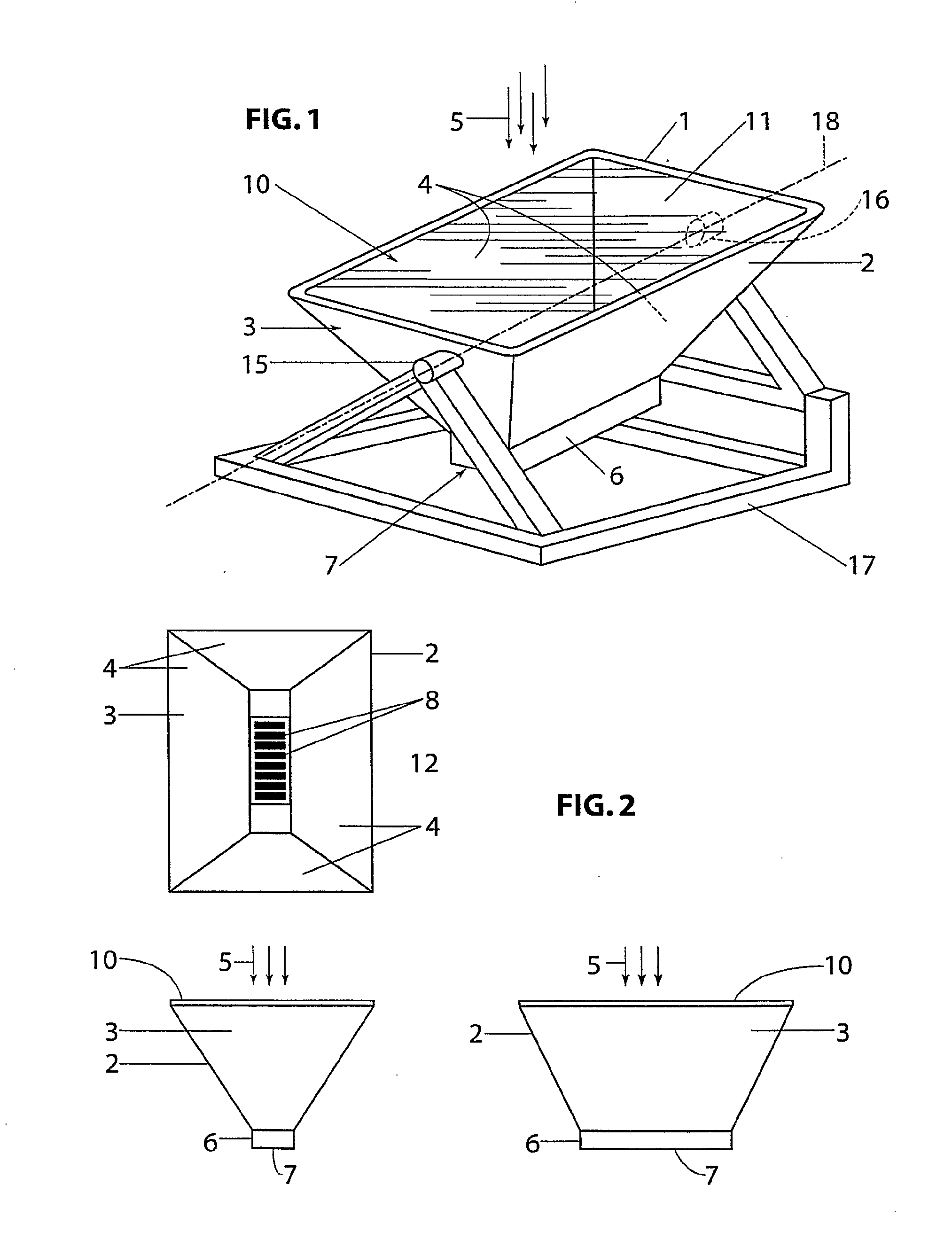
[0043]One embodiment of the present invention includes 4 elements, namely:

[0044]Fresnel Lens,

[0045]Collection Cradle with PV cell array,

[0046]Cooling System providing Preheated Water, and

[0047]Sun Tracking System

These are further disclosed herein below.

1. Overall System

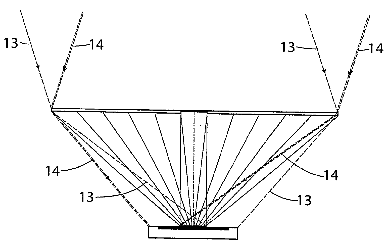
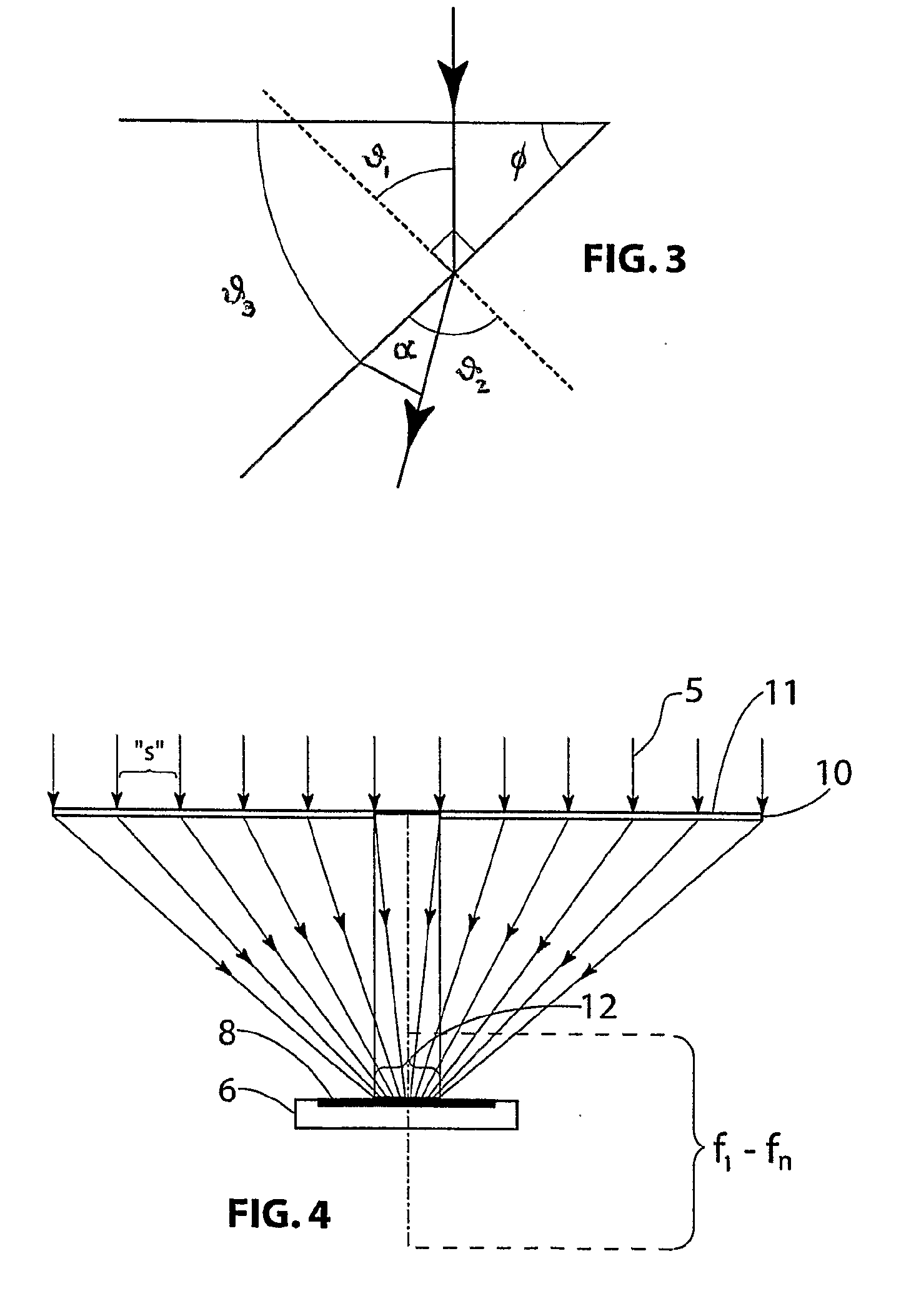
[0048]The present invention, and its various aspects:[0049]Utilizes a specifically designed Fresnel type lens to concentrate the sun's radiation onto photovoltaic cells to produce electrical energy,[0050]Applies at least one strip of photovoltaic cells to the base of a walled cradle. The length of the strip is determined by the location of the system in the world, relative to the conditions of the sun's rotation to that location. The walls of the cradle are preferably reflective to increase the energy collection by virtue of the walls reflecting additional light onto the cells and / or to offset any variation in sunlight due to clouds in the north-south direction and any seasonal variations in the latitude of the sun. T...


PUM


Abstract

A collector (2) for concentrating radiation (5), preferably solar radiation, and an energy collection system (1) that includes the collector, which concentrates the radiation along an elongate region of a body which converts the radiation into electrical and/or heat energy. A lens (10) is also disclosed for use in the system, which has a focal plane extending normally of the lens.

Description

FIELD OF INVENTION[0001]The present invention relates to an energy collection system.[0002]In one form, the invention has application for use with systems which convert solar energy to heat and / or electrical energy, such as with photovoltaic cells.[0003]It will be convenient to hereinafter describe the invention in relation to use with photovoltaic cells (PV cells), however, it should be appreciated that the present invention is not limited to that use only.BACKGROUND OF THE INVENTION[0004]It is known to use photovoltaic cells to produce electricity from photonic radiation received from the sun. The photovoltaic cells are conventionally mounted on a flat panel, beneath a protective glass layer, in an array which extends over substantially an entire face of the panel, in order to maximise electrical output. The panel may be mounted on a dual-axis tracking assembly to allow the panel to continually face the sun.[0005]There are a number of problems that currently exist in and around th...

Claims


Application Information

Patent Timeline
Patent Type & Authority Applications(United States)
IPC IPC(8): H01L31/052F24J2/54F24S23/00F24S23/30F24S23/74F24S50/20H01L31/058
CPCF24J2/06F24J2/085F24J2/5413Y02B10/10Y02B10/20Y02B10/70H01L31/0547Y02E10/44Y02E10/47Y02E10/52Y02E10/60H02S40/44H01L31/0543Y02E10/43F24S30/428F24S23/00F24S23/31F24S50/20
Inventor THOROUGHGOOD, DENNIS
Owner TECHN SOLAR
Why Eureka
Try Eureka