Controller of drive device for vehicle
a control apparatus and vehicle technology, applied in electric devices, electric control, gearing, etc., can solve the problems of unfavorable unfavorable power transmission mechanism availability, and risk of deterioration of fuel economy in some running conditions of the drive system, so as to achieve simple construction and operation of the control efficiency of the continuously variable transmission portion. , the effect of simple construction
- Summary
- Abstract
- Description
- Claims
- Application Information
AI Technical Summary
Benefits of technology
Problems solved by technology
Method used
Image
Examples
embodiment 1
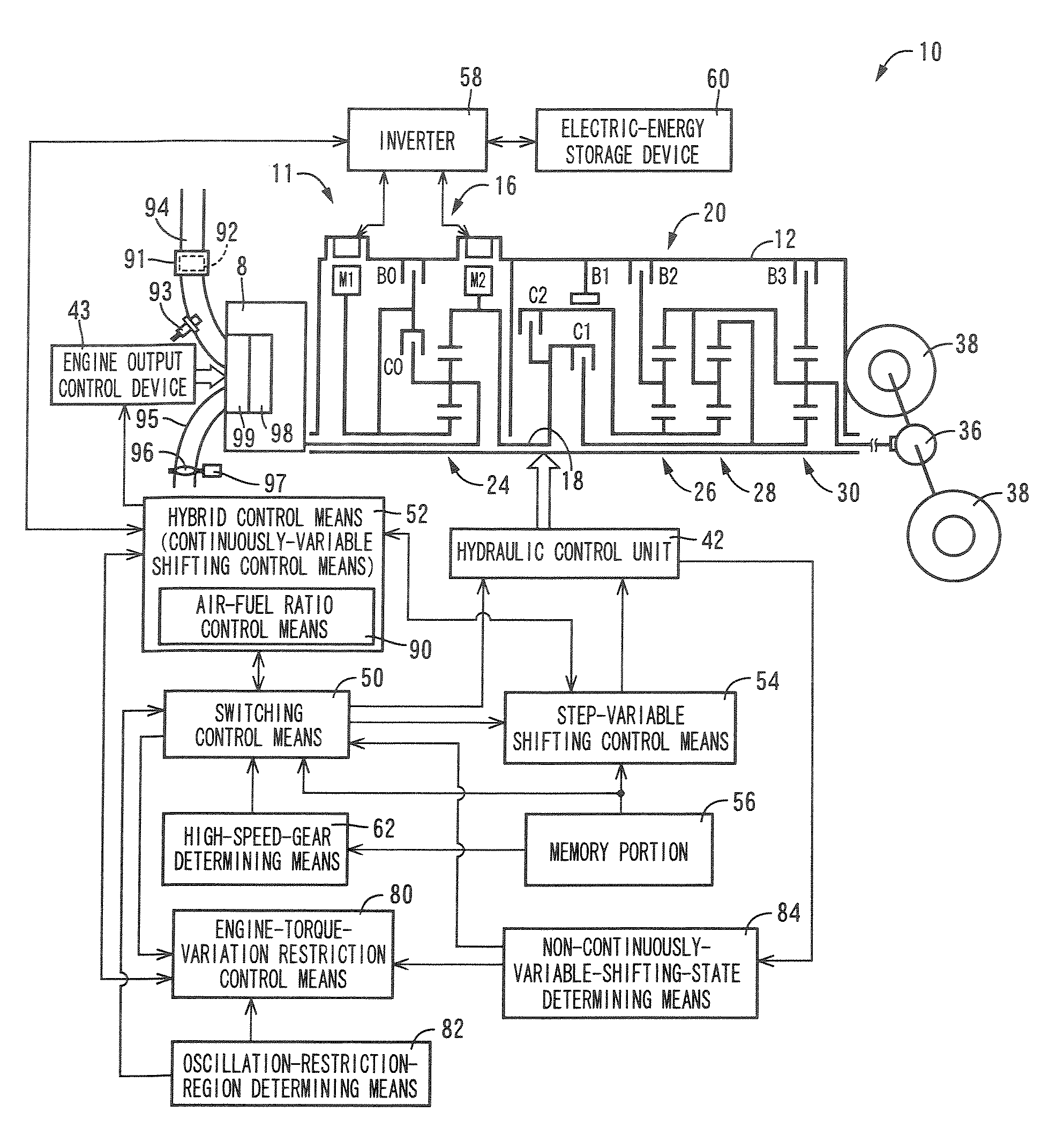
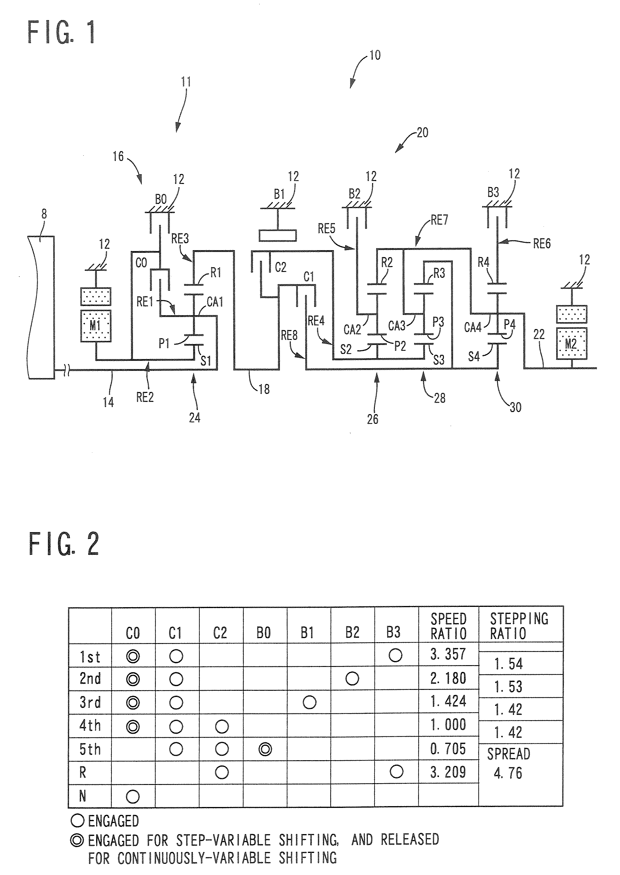
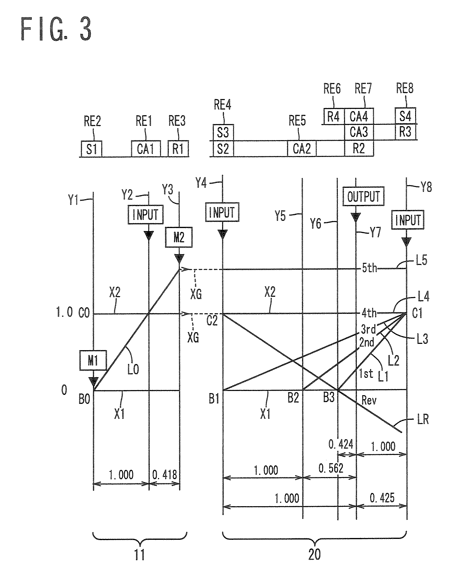
[0065]Referring to the schematic view of FIG. 1, there is shown a transmission mechanism 10 constituting a part of a drive system for a hybrid vehicle, to which a control apparatus according to one embodiment of this invention is applicable. In FIG. 1, the transmission mechanism 10 includes: an input rotary member in the form of an input shaft 14; a differential portion 11 connected to the input shaft 14 either directly, or indirectly via a pulsation absorbing damper (vibration damping device) not shown; a transmission portion functioning as a step-variable transmission in the form of an automatic transmission portion 20 disposed in a power transmitting path between the differential portion 11 and drive wheels 38 of the vehicle, and connected in series via a power transmitting member 18 (power transmitting shaft) to the transmission portion 11 and the drive wheels 38; and an output rotary member in the form of an output shaft 22 connected to the automatic transmission portion 20. Th...
embodiment 2
[0165]Referring to the schematic view of FIG. 14, there is shown an arrangement of a transmission mechanism 70 in another embodiment of this invention, and FIG. 15 a table indicating a relationship between the gear positions of the transmission mechanism 70 and different combinations of engaged states of the hydraulically operated frictional coupling devices for respectively establishing those gear positions, while FIG. 16 is a collinear chart for explaining a shifting operation of the transmission mechanism 70.
[0166]The transmission mechanism 70 includes the differential portion 11 having the first electric motor M1, power distributing mechanism 16 and second electric motor M2, as in the preceding embodiment. The transmission mechanism 70 further includes an automatic transmission portion 72 having three forward drive positions. The automatic transmission portion 72 is disposed between the differential portion 11 and the output shaft 22 and is connected in series to the differentia...
embodiment 3
[0174]FIG. 17 shows an example of a seesaw switch 44 (hereinafter referred to as “switch 44”) functioning as a shifting-state selecting device manually configured to be operable to select the differential state (non-locked state) and or non-differential state (locked state) of the power distributing mechanism 16, that is, to select the continuously-variable shifting state or step-variable shifting state of the transmission mechanism 10. This switch 44 permits the user to select the desired shifting state during running of the vehicle. The switch 44 has a continuously-variable-shifting running button labeled “STEP-VARIABLE” for running of the vehicle in the continuously-variable shifting state, and a step-variable-shifting running button labeled “CONTINUOUSLY-VARIABLE” for running of the vehicle in the step-variable shifting state, as shown in FIG. 17. When the continuously-variable-shifting running button is depressed by the user, the switch 44 is placed in a continuously-variable s...
PUM
 Abstract
Description
Claims
Application Information
 - R&D
- Intellectual Property
- Life Sciences
- Materials
- Tech Scout
- Unparalleled Data Quality
- Higher Quality Content
- 60% Fewer Hallucinations
Browse by: Latest US Patents, China's latest patents, Technical Efficacy Thesaurus, Application Domain, Technology Topic, Popular Technical Reports.
© 2025 PatSnap. All rights reserved.Legal|Privacy policy|Modern Slavery Act Transparency Statement|Sitemap|About US| Contact US: help@patsnap.com


