Open-top welding chamber

US20090230094A1Inactive Publication Date: 2009-09-17CORNE JOSEPH E

Image

  • Open-top welding chamber
  • Open-top welding chamber
  • Open-top welding chamber

Examples


Embodiment Construction

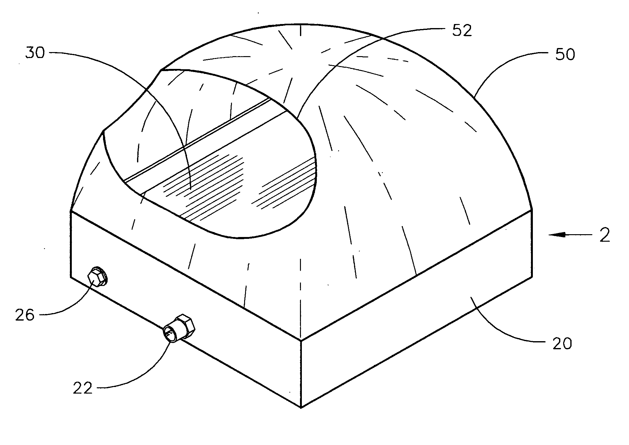
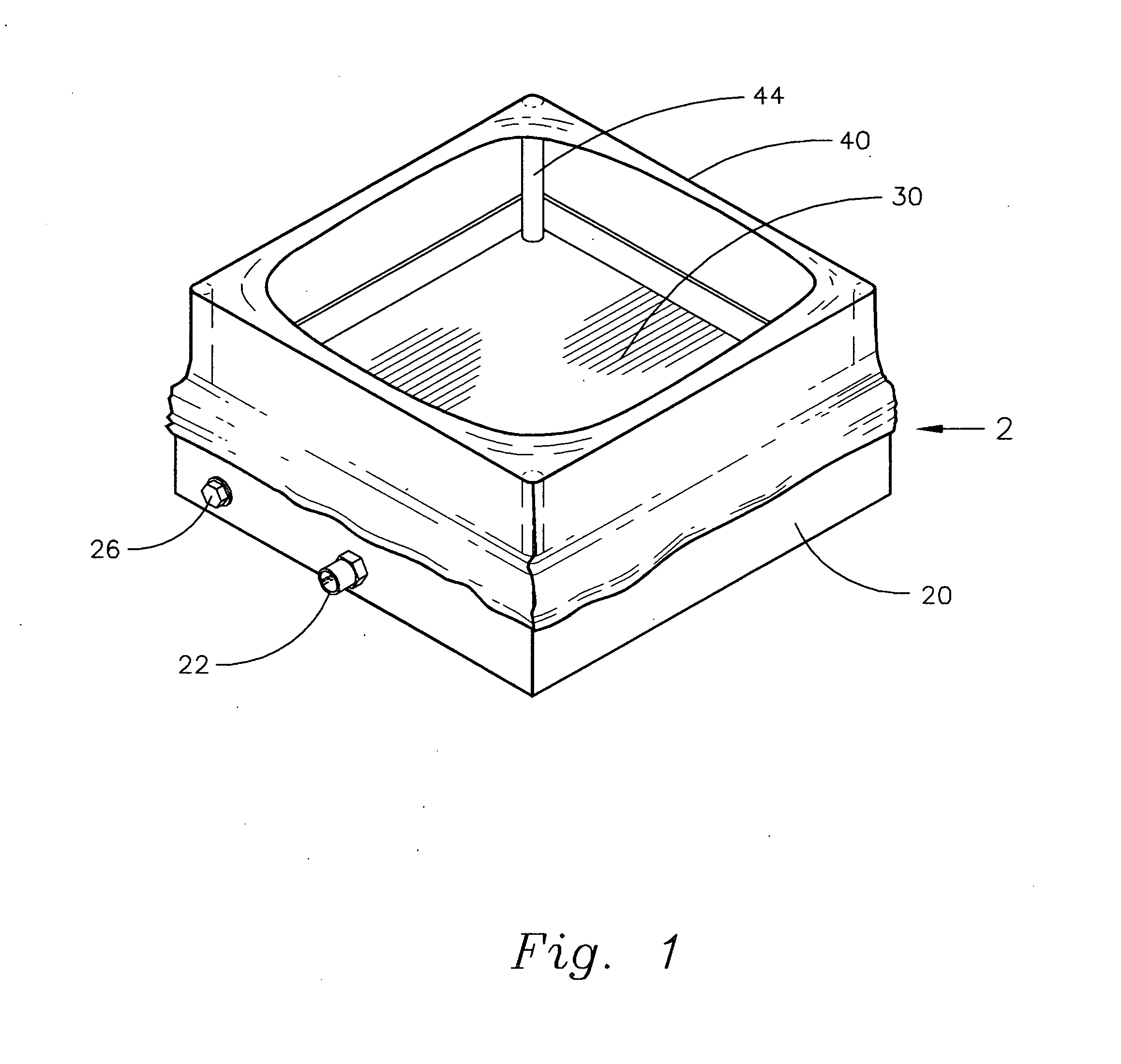
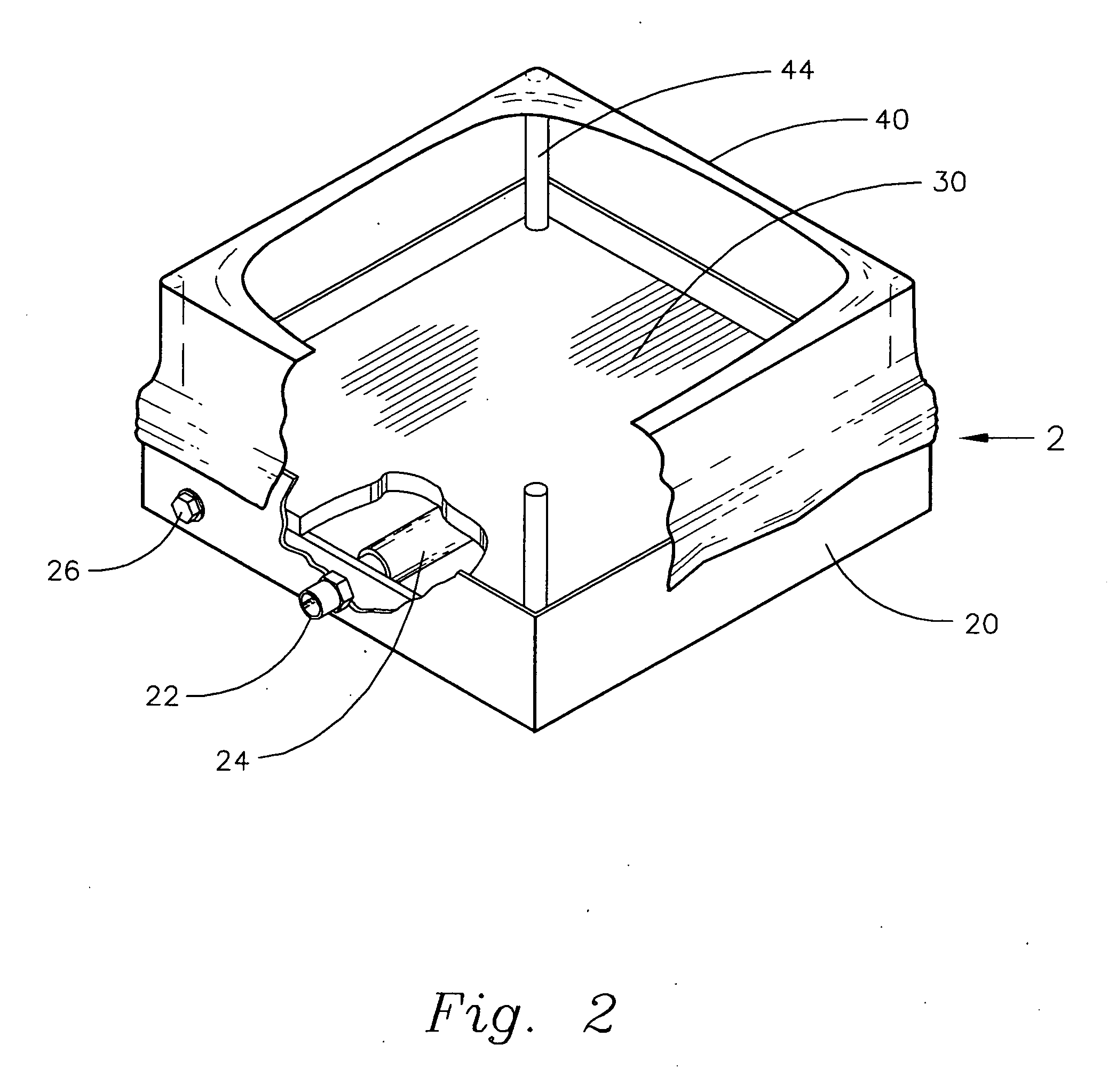
[0021]The present invention shown in FIGS. 1 & 3 is an open-top welding chamber 2 that provides a cloud of argon 64 used to exclude air from under and around a workpiece (not shown) that is to be arc-welded. It comprises an accumulation chamber 20, a welding bed 30 for supporting the workpiece to be welded, and a curtain barrier 40 constraining the argon cloud 64 (FIGS. 3 & 4) for the actual welding. The welding bed 30 must be porous and metallic. It could be made from one piece of sintered metal, or it could be a sandwich of various materials such as perforated metallic plates with a filler of steel wool or wire mesh between the plates. The curtain barrier 40 must be made of a non-porous, non-metallic material such as plastic, leather, oilcloth, or waterproof canvas to keep the argon cloud 64 in place.

[0022]FIGS. 3 & 4 illustrate the entry of pressurized argon gas 60 from a standard argon hose (not shown) into the entry port 22 of the accumulation chamber 20. The argon gas 60 conti...


PUM

PropertyMeasurementUnit
Fractionaaaaaaaaaa
Flexibilityaaaaaaaaaa
Electrical conductoraaaaaaaaaa

Abstract

A novel type of welding chamber for welding refractory metals such as titanium, that is open on the top rather than completely enclosed like other welding chambers is disclosed. Pressurized argon, an inert gas, is introduced into the bottom chamber of the device through a diffuser. The argon is then forced to travel upward through a gas-permeable welding bed formed above the accumulation chamber, the welding bed made from a conductive and gas-permeable material. The present invention creates an argon cloud of substantially 100% argon for welding titanium and other refractory metals therein. The argon cloud is constrained by a curtain barrier and the property that argon is heavier than air. The argon cloud substantially stays in place when not disturbed by movement of air above it. Workpieces are placed into the argon cloud and onto the welding bed to be welded.

Description

FIELD OF THE INVENTION[0001]This invention relates to inert-gas backup devices and enclosures used in the arc welding of titanium and other refractory metals.BACKGROUND OF INVENTION[0002]Many exotic metals, such as titanium, cannot be welded in the presence of air without producing a weak and discolored weld. An inert gas such as argon may be used to displace the air surrounding the weld, thereby solving the problem. There are several popular solutions in use.[0003]“Welding chambers” are available in the marketplace. The primary component of a welding chamber is either a rigid box-like enclosure or a semi-flexible balloon-like enclosure. In either case the enclosure is a sealed unit with the purpose of constraining a volume of gas. Workpieces to be welded are placed inside the chamber through a door, or zipper, or some other means of access. An arc-welding torch is present in the chamber and accessed with air-tight gloves provided in the chamber walls. The chamber is flooded with an...

Claims


Application Information

Patent Timeline
17 Sep 2009
Publication
US20090230094A1
IPC
B23K9/32; B23K35/38
CPC
B23K2203/14; B23K9/325; B23K2103/14
Inventors
CORNE, JOSEPH E.