Welding head carrier for use in welding inner surface of tube

a welding head and tube technology, applied in the direction of soldering apparatus, manufacturing tools,auxillary welding devices, etc., can solve the problems of severe limitations in behavior, viewing and workability, limited welding working time, etc., and achieve the effect of reducing costs, convenient mounting and extended use rang

Inactive Publication Date: 2009-09-17
KOREA HYDRO & NUCLEAR POWER CO LTD
View PDF3 Cites 14 Cited by
  • Summary
  • Abstract
  • Description
  • Claims
  • Application Information

AI Technical Summary

Benefits of technology

[0009]Therefore, it is one object of the present invention to provide a welding head carrier suitable for use in welding the inner surface of a tube in which fixing units can be adjusted in length depending on the size of the tube, thus eliminating the need for the rebuilding or replacement of the welding head carrier, which results in cost reduction, and a welding head can be easily mounted, regardless of manufacturers of the welding head, thus achieving remarkably extended range of use.

Problems solved by technology

As a result, radioactive contamination around the steam generator is inevitable, which causes limited working time for the welding.
Further, workers who are exposed to these dangerous working conditions should wear bulky and heavy protective clothing and safe equipment, which will be accompanied by severe limitations in behavior, viewing and workability.
When the welding head and the track are replaced with new models, however, the welding head carrier may be incompatible with the new models.
This incompatibility requires modification of the welding head carrier and makes it impossible to use the welding head carrier any more.
However, since the conventional welding apparatus has no function to move the welding head in the lengthwise direction of a tube, the track must be precisely mounted along a welding line to weld the inner surface of the tube along the welding line.
For these reasons, the conventional welding apparatus suffers from problems, such as inconvenience and difficulty in precisely installing the track.
Further, when the welding head moves along the track in a friction manner, welding defects may occur due to uncontrollable slipping of the welding head from the track.

Method used


Image

  • Welding head carrier for use in welding inner surface of tube
  • Welding head carrier for use in welding inner surface of tube
  • Welding head carrier for use in welding inner surface of tube

Examples


Embodiment Construction

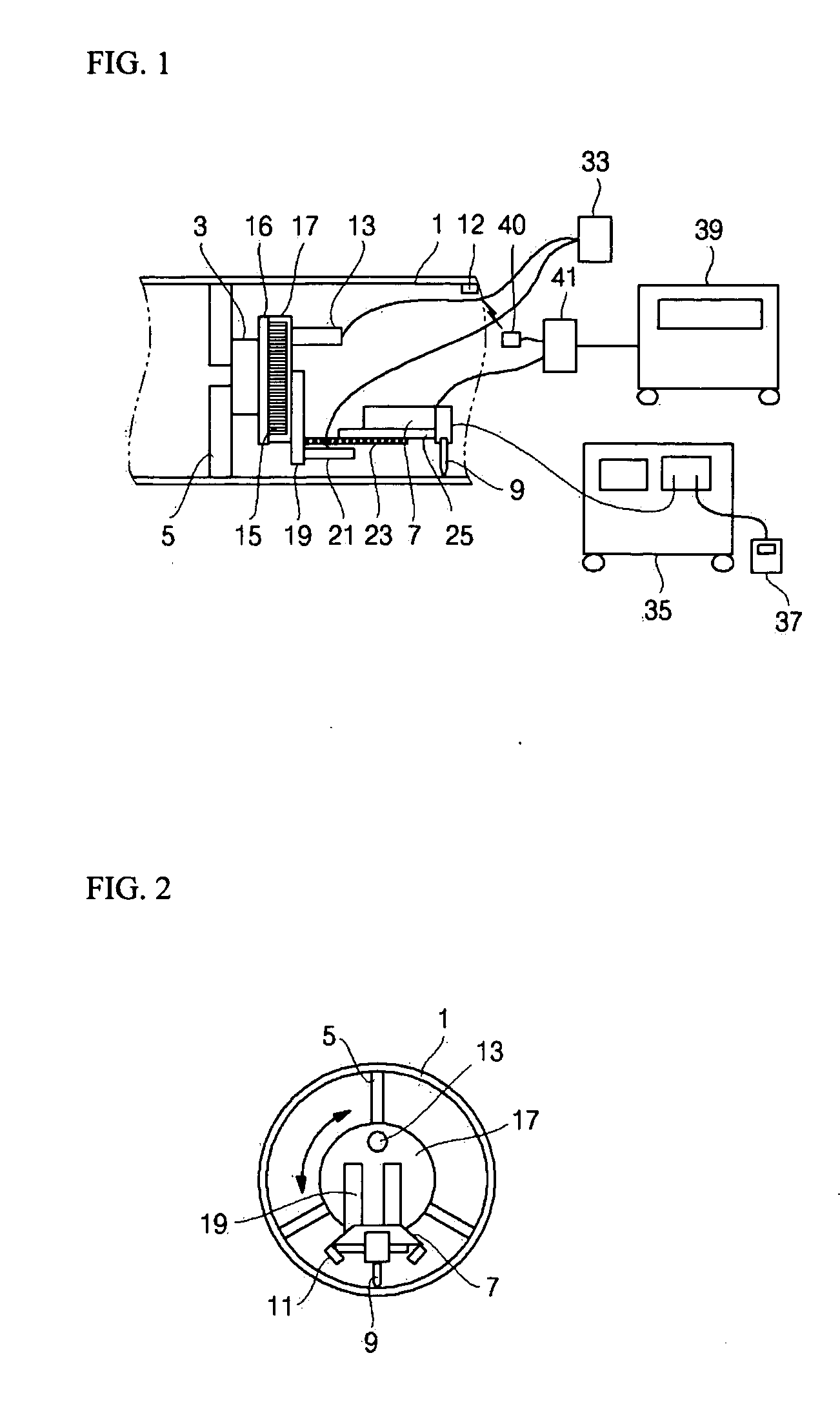
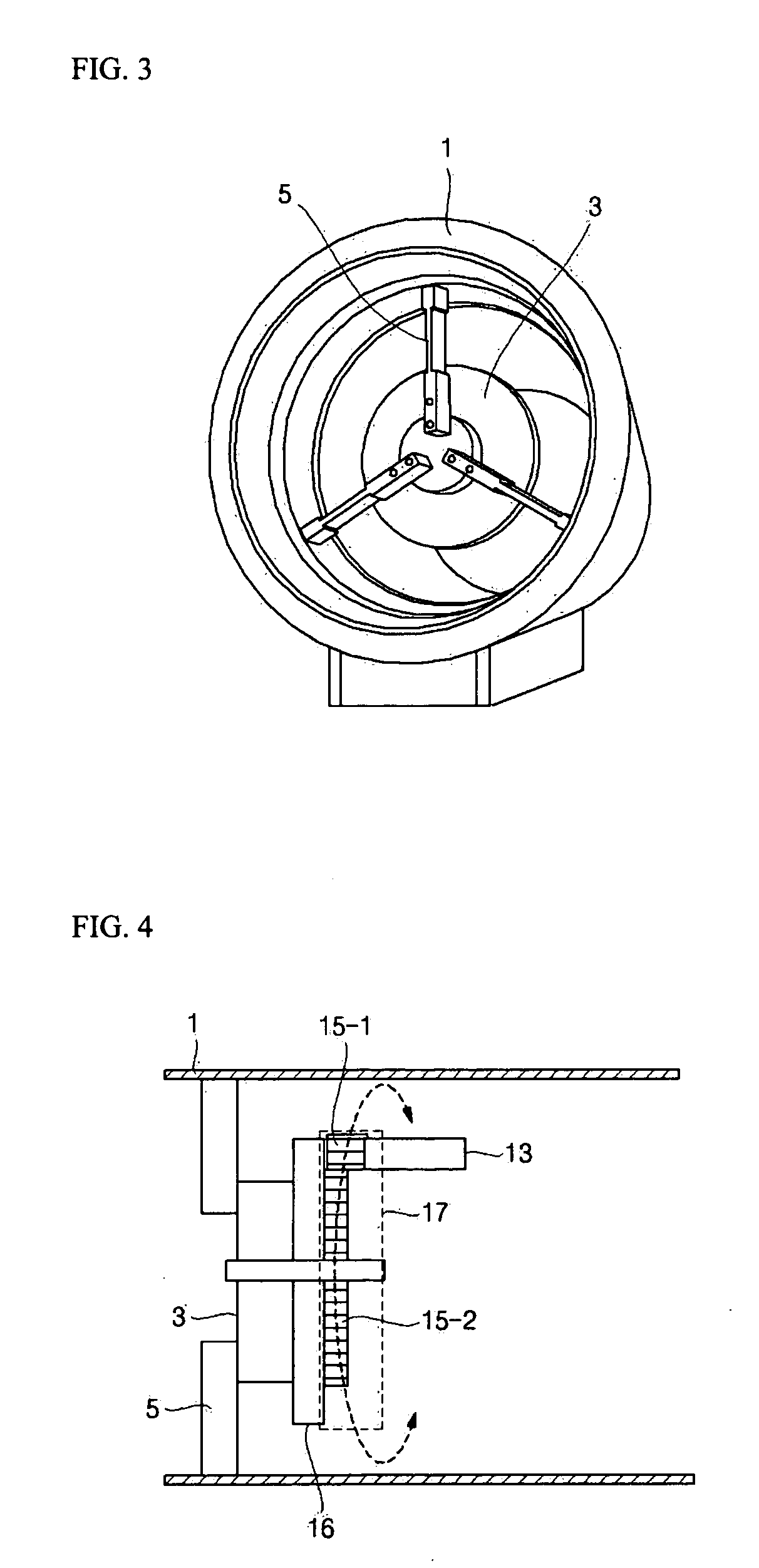
[0027]Exemplary embodiments of the present invention will now be described in detail with reference to the accompanying drawings.

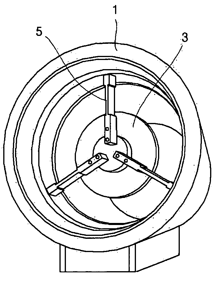
[0028]Referring to FIG. 1 to FIG. 6, the welding head carrier according to an embodiment of the present invention comprises: a universal chuck 3 as a main body; a plurality of fixing units 5 attached to the universal chuck 3 to fix the main body to the inner surface of the tube 1; a rotary motor 13 to generate a driving force for welding the inner surface of the tube 1 in the circumferential direction of the tube 1; a rotary driver 15 for the transmission of the driving force from the rotary motor 13; a rotary cover 17 to protect the rotary driver 15, to allow a forward / backward driving unit to be attached thereto, to receive the driving force transmitted from the rotary driver 15 and to rotate in the circumferential direction of the tube 1; a rotary unit-attaching bar 19 connected to the rotary cover 17; a forward / backward driving motor 21 to generate a d...


PUM

PropertyMeasurementUnit
driving forceaaaaaaaaaa
lengthaaaaaaaaaa
sizeaaaaaaaaaa

Abstract

A welding head carrier for use in welding the inner surface of a tube includes inter alia a welding head provided with a welding torch and a camera, a wireless camera mounted at the inner side of the tube to monitor whether cables are entangled, a wireless receiver for receiving wirelessly an image from the wireless camera, including a camera controller for controlling the camera and the wireless receiver, display for displaying the welding operation and the inside of the tube. Fixing units can be adjusted in length depending on the size of the tube, thus eliminating the need for the rebuilding or replacement of the welding head carrier, leading to cost savings. The welding head can be easily mounted, regardless of size and configuration of the welding head, and the range of use of the welding head carrier can be extended.

Description

BACKGROUND OF THE INVENTION[0001]1. Field of the Invention[0002]The present invention relates generally to a welding head carrier for use in welding the inner surface of a tube and more specifically relates to a welding head carrier that can be used in welding the inner surface of a connecting portion of a main tube (i.e. a reactor coolant loop) when a steam generator of a nuclear power plant is replaced with a new one.[0003]2. Description of the Related Art[0004]In general, a steam generator of a nuclear power plant is one of the most crucial units for generating steam required to produce electric power from a steam turbine and a power generator, and allows a high-temperature, high-pressure radioactive primary coolant from a nuclear reactor to flow through a tube such that cold feed water surrounding the tube is heated to generate steam, after which the steam is supplied to the turbine.[0005]When it is intended to replace the steam generator with a new one, welding is conducted aft...

Claims


Application Information

Patent Timeline
Patent Type & Authority Applications(United States)
IPC IPC(8): B23K37/02B23K9/028
CPCB23K9/0284B23K9/32B23K2201/06B23K37/0276B23K37/0217B23K2101/06
Inventor YANG, JUN SEOGKIM, TAE RYONGYOO, SEUNG YOUNGCHOI, SUK SOON
Owner KOREA HYDRO & NUCLEAR POWER CO LTD
Why Eureka
Try Eureka