
Compact remote tuned antenna

a remote tuned, compact technology, applied in the direction of antennas, antenna details, electrical apparatus, etc., can solve the problems of many unsatisfactory problems, continued development of such antenna devices, etc., and achieve the effect of high rf current level, high rf power level, and efficient handling of high rf power levels

Inactive Publication Date: 2009-09-17
LARONDA MICHAEL
View PDF2 Cites 14 Cited by
  • Summary
  • Abstract
  • Description
  • Claims
  • Application Information

AI Technical Summary

Benefits of technology

[0009]An improved compact antenna embodying the disclosure may replace the high radiation efficiency, full size electrical length dipole and monopole antennas commonly used in VLF to microwave frequency ranges, and can efficiently transmit RF energy in a reduced volume, length, width and height package, both in temporary and in permanent applications. Such a compact antenna may also have remote controlled tuning over entire bandwidth ranges of the VLF, HF and microwave frequency bands.
[0010]Furthermore, in accordance with the disclosure, an improved antenna system is provided for introducing RF energy at high RF current levels to an antenna-radiating element, which has a low series inductance value to reduce voltage across the element. Such an improved antenna system may be compact and efficient and have an improved receive aperture that can support remote indoor or outdoor operation.
[0012]In addition, an RF tuning apparatus is provided for tuning a compact antenna that can efficiently handle high RF power levels of greater than about 1500 watts RMS, and may remotely tune a compact antenna system at high RF current levels. In an embodiment, this RF tuning apparatus has a minimum number of moving parts, may be configured for a number of bands and be tuned relatively quickly within a given band, and may be housed in a small waterproof box at an antenna location remote from the transmitter and receiver.
[0013]In accordance with the disclosure, a simple and reliable parallel interface capability may be provided to a wide variety of remotely located computer devices in order to support automatic program control and turning of an antenna system.

Problems solved by technology

Attempts to improve and develop such antenna devices have continued in more recent years with only moderate success.
However, the development of an omni-directional antenna with improved low radiation angle and horizontal polarization characteristics still leaves much to be desired.

Method used


Image

  • Compact remote tuned antenna
  • Compact remote tuned antenna
  • Compact remote tuned antenna

Examples


Embodiment Construction

[0048]The term “electrical length,” when used herein, means the length of a conductor corrected for the speed of light in that conductor (a wire or other type of conductor, or transmission line device).

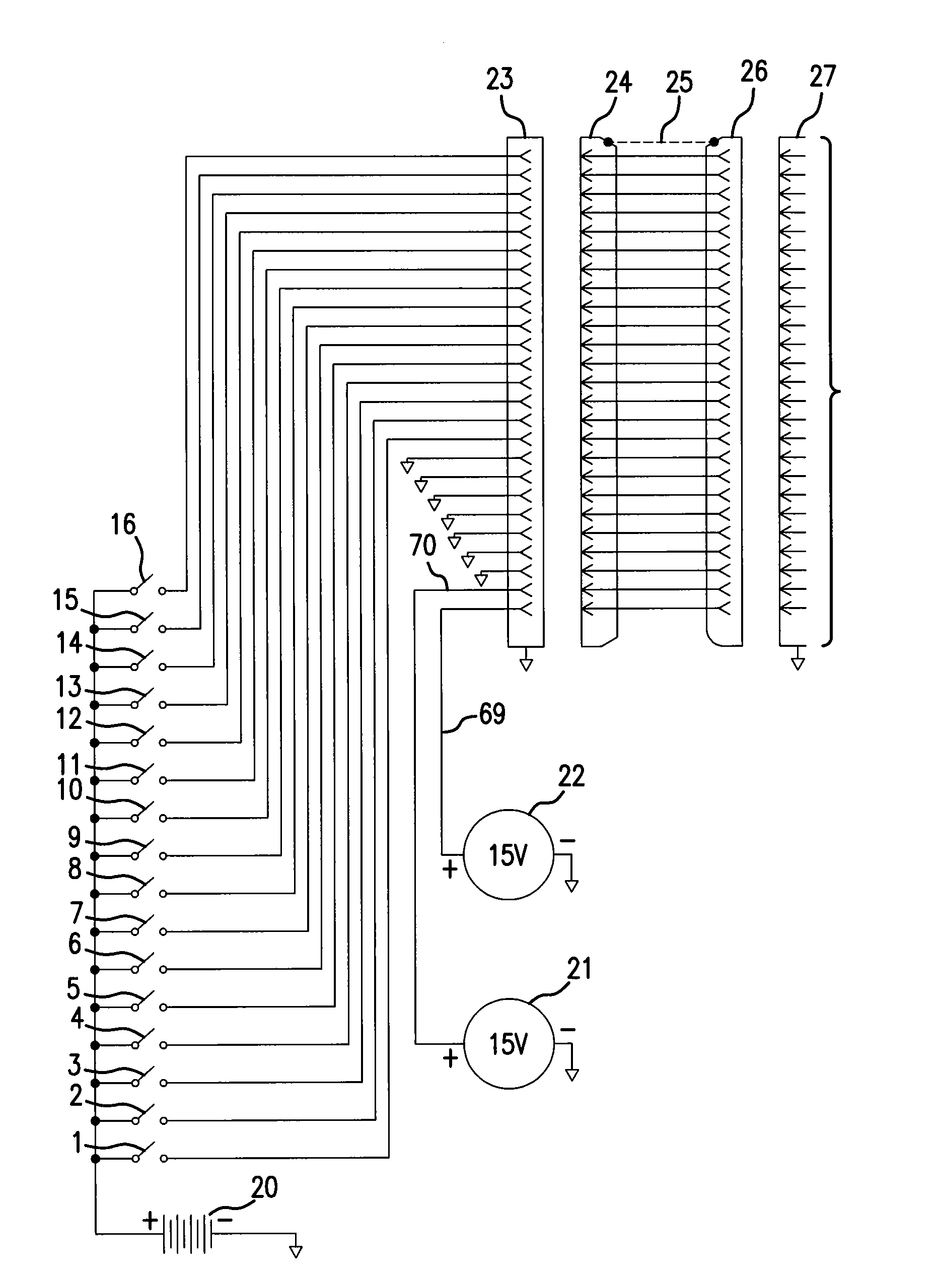
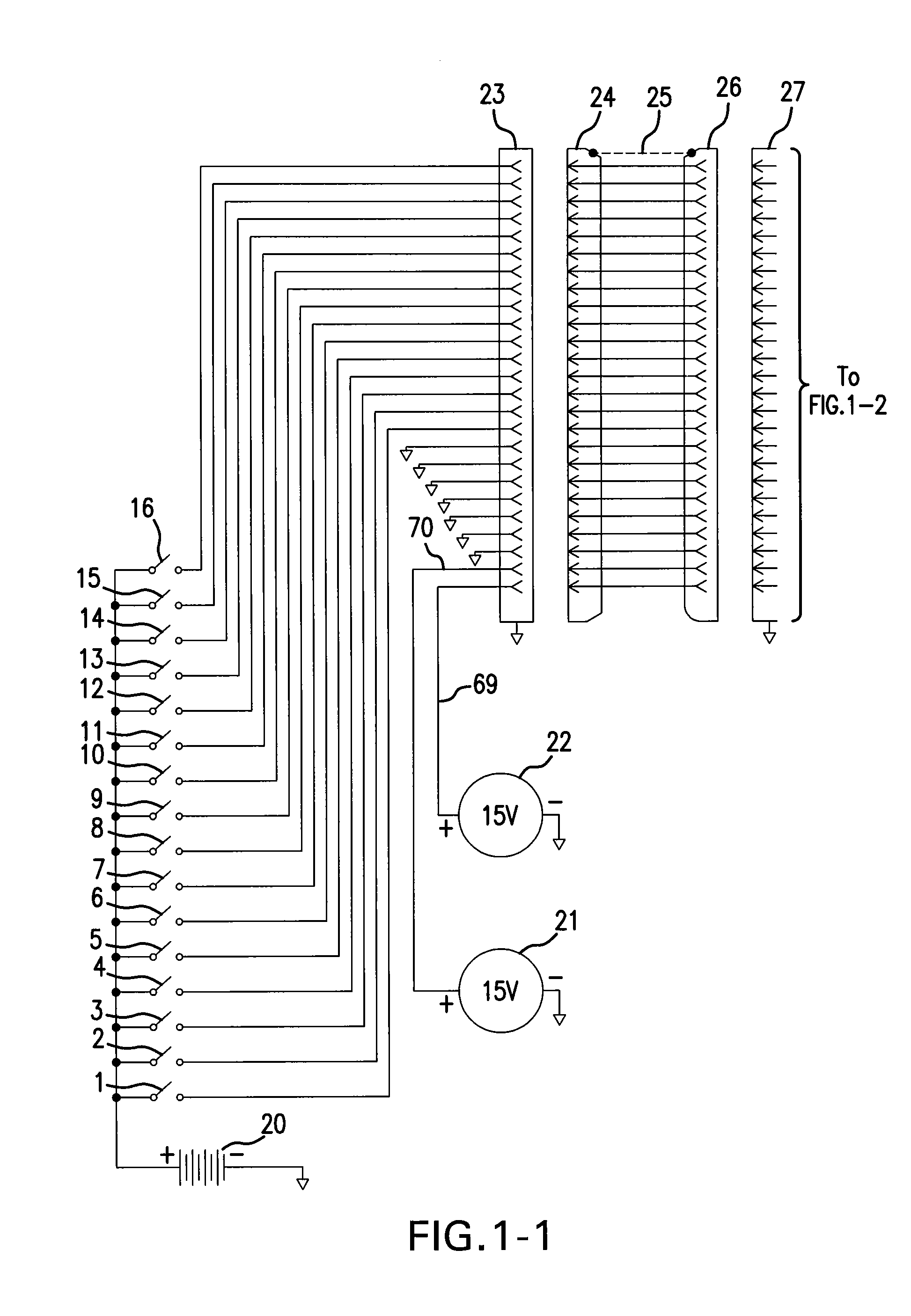
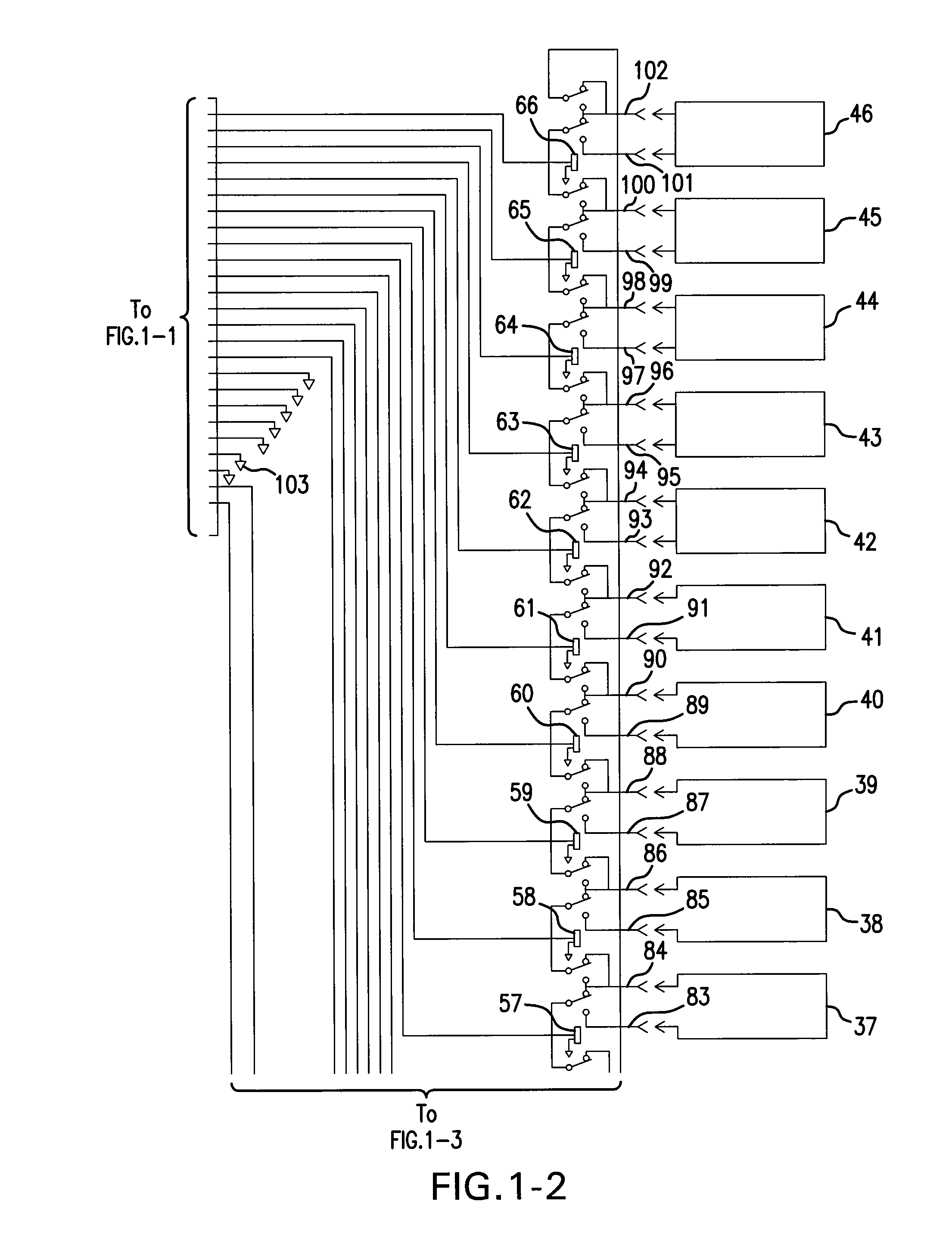
[0049]In the embodiments described herein, an electromechanical relay or other switch device is used to control, remotely and by a parallel binary bit pattern, one or more arbitrary radiating structures. These structures are formed of series connected, absolute binary sequence electrical length radiating elements in a main circuit loop; the main loop is characterized by a total main loop electrical length. The radiating arbitrary structures are formed from individual electrical length elements, and / or sets of elements insulated and isolated from each other. These binary electrical length elements may also be insulated and isolated by 1:1 balun or other transformer devices. The binary length elements may be connected to switch devices by wire or coax cable. The binary controlled switch...


PUM


Abstract

A compact electrically long antenna including a manual or computer remote controlled tuning system using switched electrical length capable of operation at high RF power levels. An electromechanical relay or other switch device provides remote control (by a parallel binary bit pattern over great distance) of radiating structures formed of series connected absolute binary sequence electrical length radiating elements in a main circuit loop having a total electrical length. These radiating structures are formed from individual elements, and sets of individual elements, insulated and isolated from each other. The binary controlled switch devices may unshort (connect) and short out (bypass) binary length elements in the main loop circuit. The electrical length of the main loop circuit can be set to a desired length, from a maximum total length of all binary length elements in series to a minimum length where all binary elements are shorted out and effectively bypassed.

Description

CROSS REFERENCE TO RELATED APPLICATIONS[0001]This application claims the benefit of U.S. Provisional Application No. 61 / 065,788, filed Feb. 14, 2008.FIELD OF THE DISCLOSURE[0002]This disclosure relates to antennas which are compact and electrically long, are effective for frequencies from long wave to microwave, and have remotely tuned narrow bandwidths for use in radio communications. More specifically, the disclosure relates to compact antenna devices including planar, coplanar and combined planar / coplanar sets of radiating / receiving elements made of spaced apart conducting loops.BACKGROUND OF THE DISCLOSURE[0003]The Amateur Radio Service of the United States and Amateur Radio Services of other countries are often the only communications services that remain working after the occurrence of natural and other disasters. There is a need in these services for a compact light weight antenna that can be easily stored in a hardened structure and then, when needed under post disaster cond...

Claims


Application Information

Patent Timeline
Patent Type & Authority Applications(United States)
IPC IPC(8): H01Q7/00H01Q1/50
CPCH01Q7/005
Inventor LARONDA, MICHAEL
Owner LARONDA MICHAEL
Learn More