
Liquid crystal display device

Active Publication Date: 2009-09-17
JAPAN DISPLAY CENT INC
View PDF3 Cites 5 Cited by
  • Summary
  • Abstract
  • Description
  • Claims
  • Application Information

AI Technical Summary

Benefits of technology

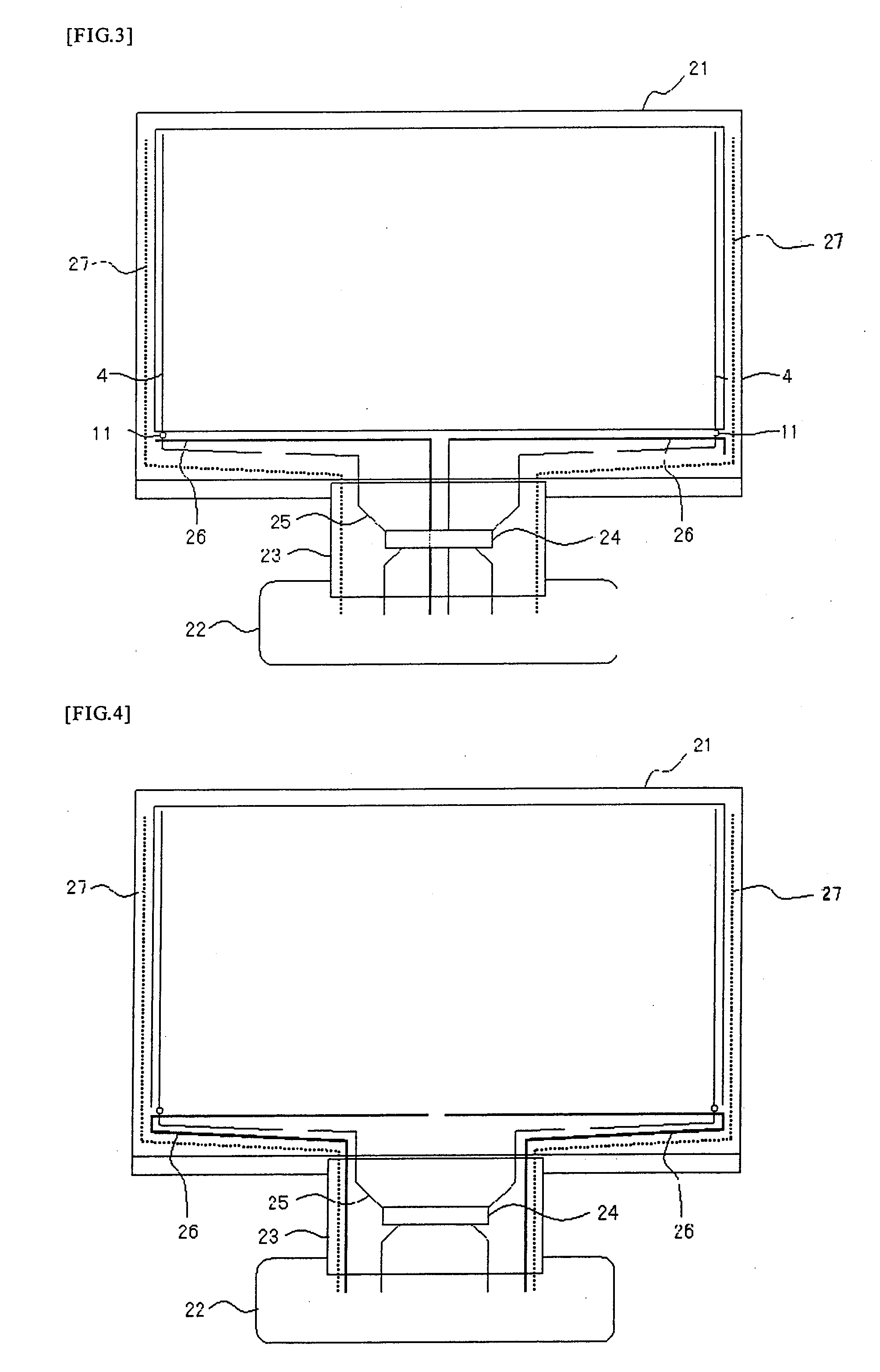
[0013]According to the present invention, as described above the control lines formed across a region in which the drive IC has been mounted on the flexible wiring substrate and drawn from a center of the flexible wiring substrate onto the liquid crystal display panel for supplying at least a power source for driving the analog switch circuit or a control signal, and the length of the control lines can be minimized.
[0014]According to the present invention, the length of the control lines for supplying the power source or control signal to the analog switch circuit can be suppressed to the minimum, and it is possible to suppress a voltage drop by interconnection resistance and suppress signal delay and signal attenuation, thereby enabling provision of a high-grade liquid crystal display device exhibiting no image degradation. Also, according to the present invention, in performing the signal line selection drive by the analog switch circuit on the array substrate, even when the flexible wiring substrate having mounted thereon the drive IC for supplying a video signal is installed only at one place, it is possible to supply the power source or control signal to the analog switch circuit without a voltage dropping and signal delay by interconnection resistance.

Problems solved by technology

In this case, when a division control signal lines for supplying the power sources and control signals to the switching circuit is pulled along from the opposite end portions of the flexible wiring substrate having the drive IC mounted thereon, the wiring length on the array substrate becomes long to possibly entail a problem of the voltage depression owing to interconnection resistance, the delay signals, and attenuation of the control signals.
Particularly in the case of forming the analog switch circuit on the array substrate and performing a signal line selection drive method that switches signal lines for supplying the video signals, based clock frequency is high and easy to make noise, and the delay signals and attenuation of the signals possibly affects greatly the quality of images to be displayed on the liquid crystal display panel.

Method used


Image

  • Liquid crystal display device
  • Liquid crystal display device
  • Liquid crystal display device

Examples


Embodiment Construction

[0020]An embodiment of the liquid crystal display device according to the present invention will be described hereinafter with reference to the drawings.

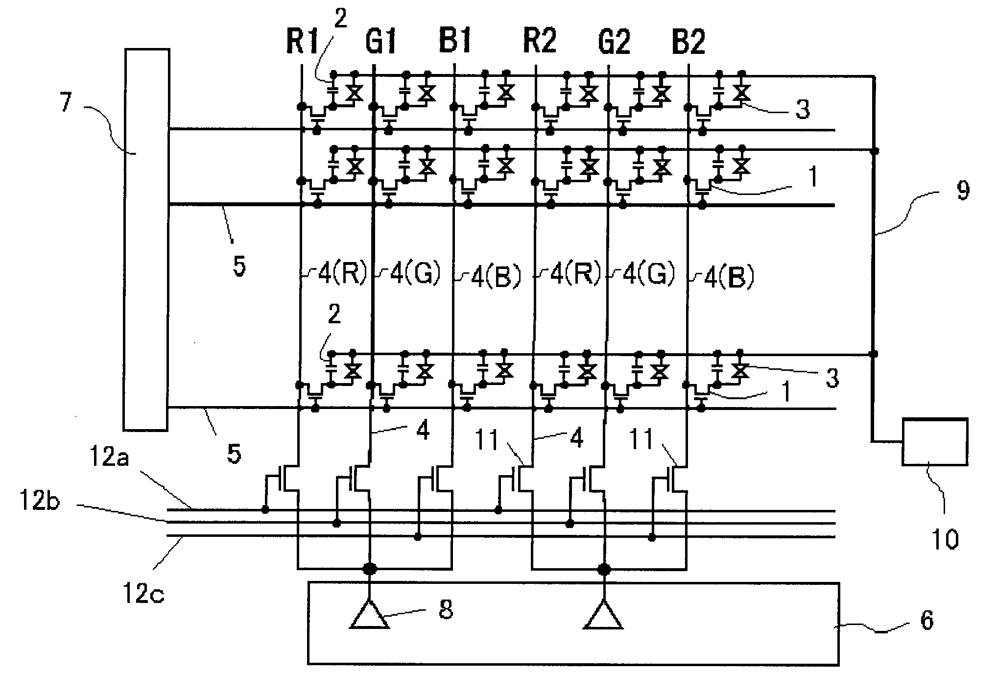
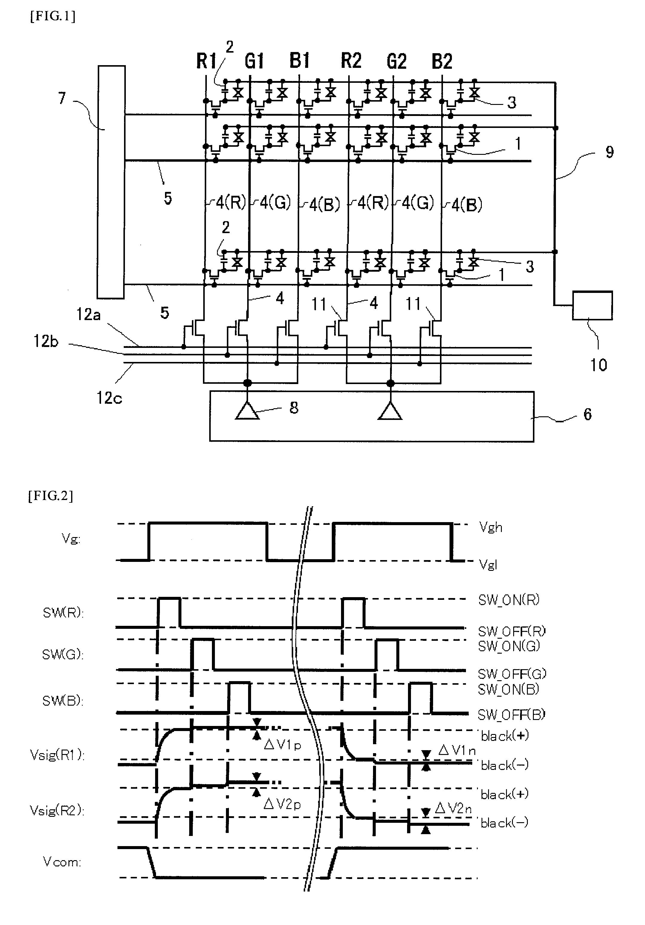
[0021]First, the schematic configuration of a liquid crystal display device having a system of signal line selection drive method by an analog switch circuit will be described. FIG. 1 shows an example of the liquid crystal display device having the system of signal line selection drive by the analog switch multiplexer circuit.

[0022]The liquid crystal display device is configured such that pixel transistors 1 comprising n-channel transistors for driving pixel electrodes are arranged in a matrix form. In the case of a color liquid crystal display device, for example, one pixel is constituted by three pixel electrodes driven by each three pixel transistors 1 corresponding respectively to red (R), green (G) and blue (B) colors. Of the three color pixel transistors, the red pixel transistors 1 are connected respectively to signal lines R...


PUM


Abstract

A liquid crystal display device comprising a liquid crystal display panel 21 having pixels each disposed on an intersection between plural scan lines and plural signal lines, a flexible wiring substrate having mounted thereon a drive IC 24 electrical connected to the liquid crystal display panel 21 for supplying video signals via video signal lines, to one video signal line of which N number of the signal lines are allocated, wherein N is an integer of two or more, an analog switch circuit switch-connected to a signal line selected from the N number of the signal lines in each of the video signal lines, and the control lines 26 formed across a region in which the drive IC 24 has been mounted on the flexible wiring substrate 23 and drawn from a center of the flexible wiring substrate 23 onto the liquid crystal display panel for supplying at least a power source for driving the analog switch circuit or a control signal.

Description

BACKGROUND OF THE INVENTION[0001]1. Field of the Invention[0002]The present invention relates to a liquid crystal display device and particularly to an improvement in the control lines that controls an analog switch circuit in the liquid crystal display device having a system of apportioning to a plurality of signal lines video signals supplied from video signal lines.[0003]2. Description of the Prior Art[0004]In recent years, liquid crystal display devices having features of light weight, small thickness and small power consumption have widely been used as liquid crystal display devices for information equipment, such as personal computers and word processors, and for video equipment, such as television sets, video cameras, digital cameras and car navigation systems. A liquid crystal display device has a liquid crystal display panel having liquid crystal materials sealed between two substrates (an array substrate and a counter electrode) and, in the liquid crystal display panel, a ...

Claims


Application Information

Patent Timeline
IPC IPC(8): G09G3/36
CPCG09G3/3648G09G2320/0223G09G2300/0426
Inventor MATSUMOTO, TOMOHIROTSUKAMOTO, TAKAYOSHI
Owner JAPAN DISPLAY CENT INC
Learn More