Measuring method, stage apparatus, and exposure apparatus

a technology of stage apparatus and exposure apparatus, which is applied in the direction of photomechanical apparatus, instruments, printers, etc., can solve the problems of irregular fluctuations in gas flow and interferometer turbulence to a certain exten

Active Publication Date: 2009-09-17
NIKON CORP
View PDF17 Cites 34 Cited by
  • Summary
  • Abstract
  • Description
  • Claims
  • Application Information

AI Technical Summary

Benefits of technology

[0009]According to a first aspect of the present invention, there is provided a measuring method that measures a displacement of a movable member with respect to a predetermined member, the method comprising: providing a scale to one of the predetermined member and the movable member and providing a plurality of detectors to the other one, the detectors being capable of detecting the scale; supporting the scale or the plurality of detectors provided to the predetermined member with a support member, a coefficient of linear thermal expansion of which is smaller than that of the movable member; and measuring the displacement of the movable member based on the detection results of the plurality of detectors.

Problems solved by technology

Nevertheless, when a stage to be measured—particularly a wafer stage of a scanning type exposure apparatus—is moved at a high speed in the vertical and transverse directions, there is a problem in that the movement of the stage causes irregular fluctuations in the gas flow, and consequently interferometer turbulence remains to a certain extent.

Method used


Image

  • Measuring method, stage apparatus, and exposure apparatus
  • Measuring method, stage apparatus, and exposure apparatus
  • Measuring method, stage apparatus, and exposure apparatus

Examples


first embodiment

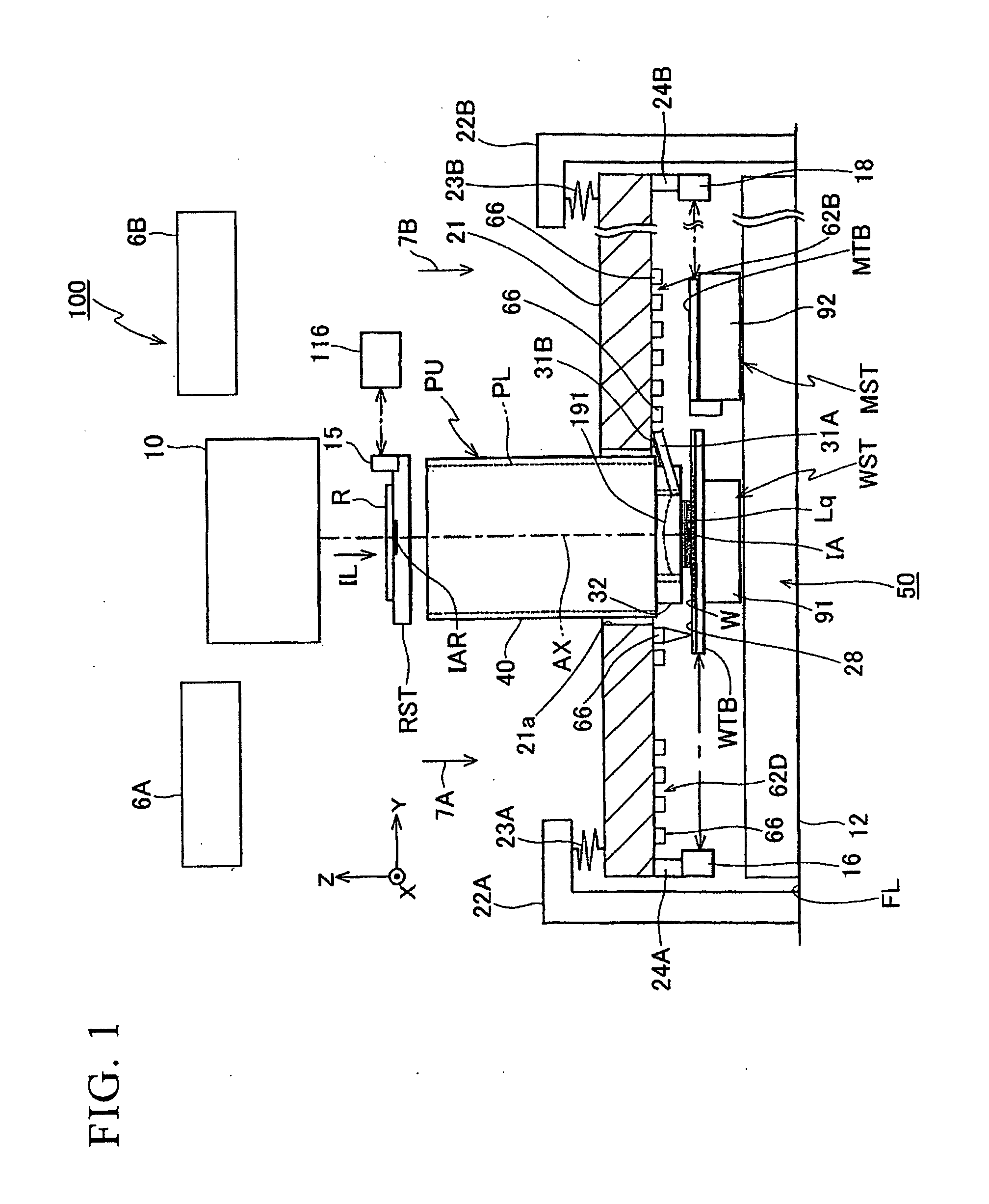
[0042]The following explains a preferred first embodiment of the present invention, referencing FIG. 1 through FIG. 11.

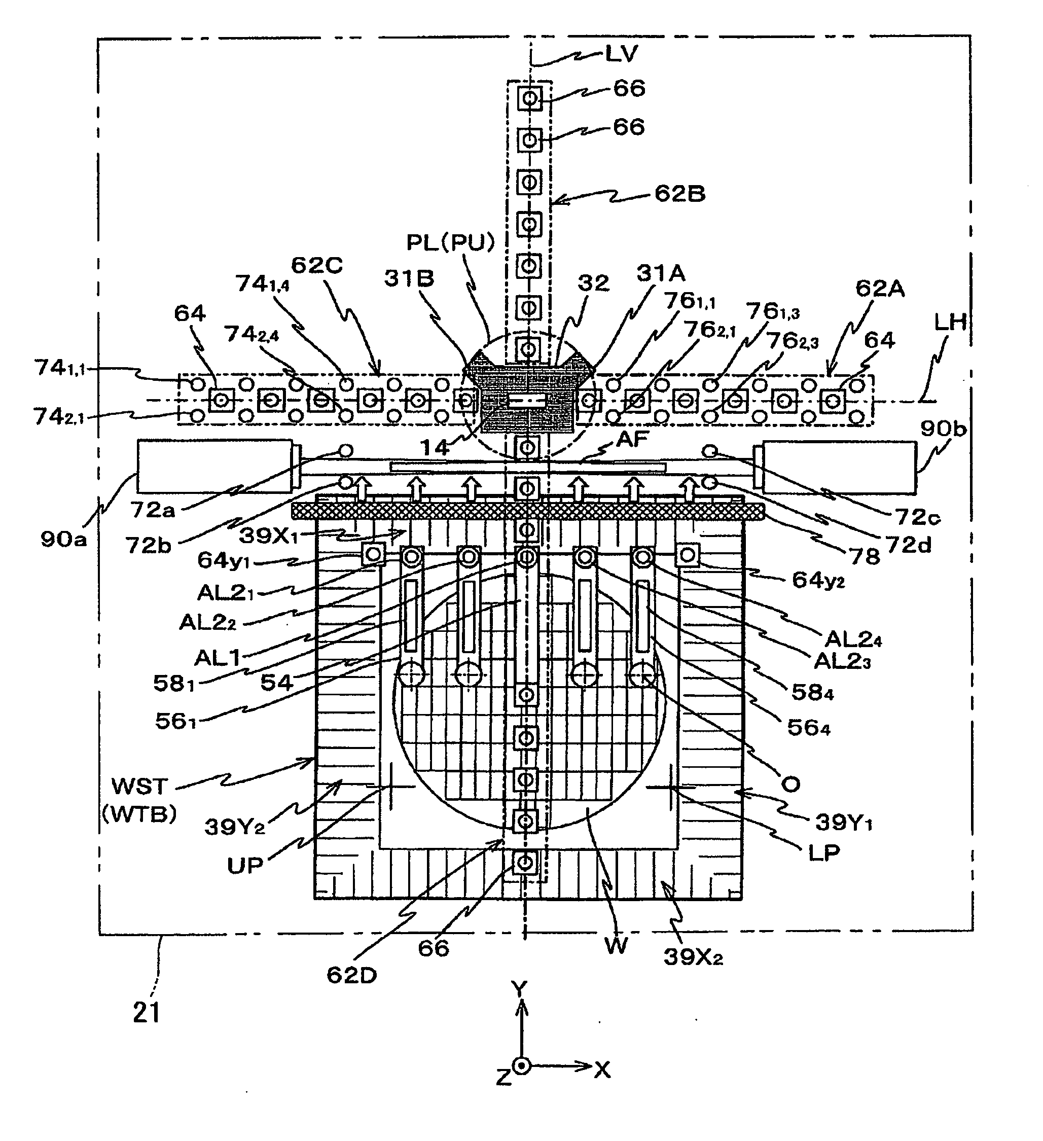
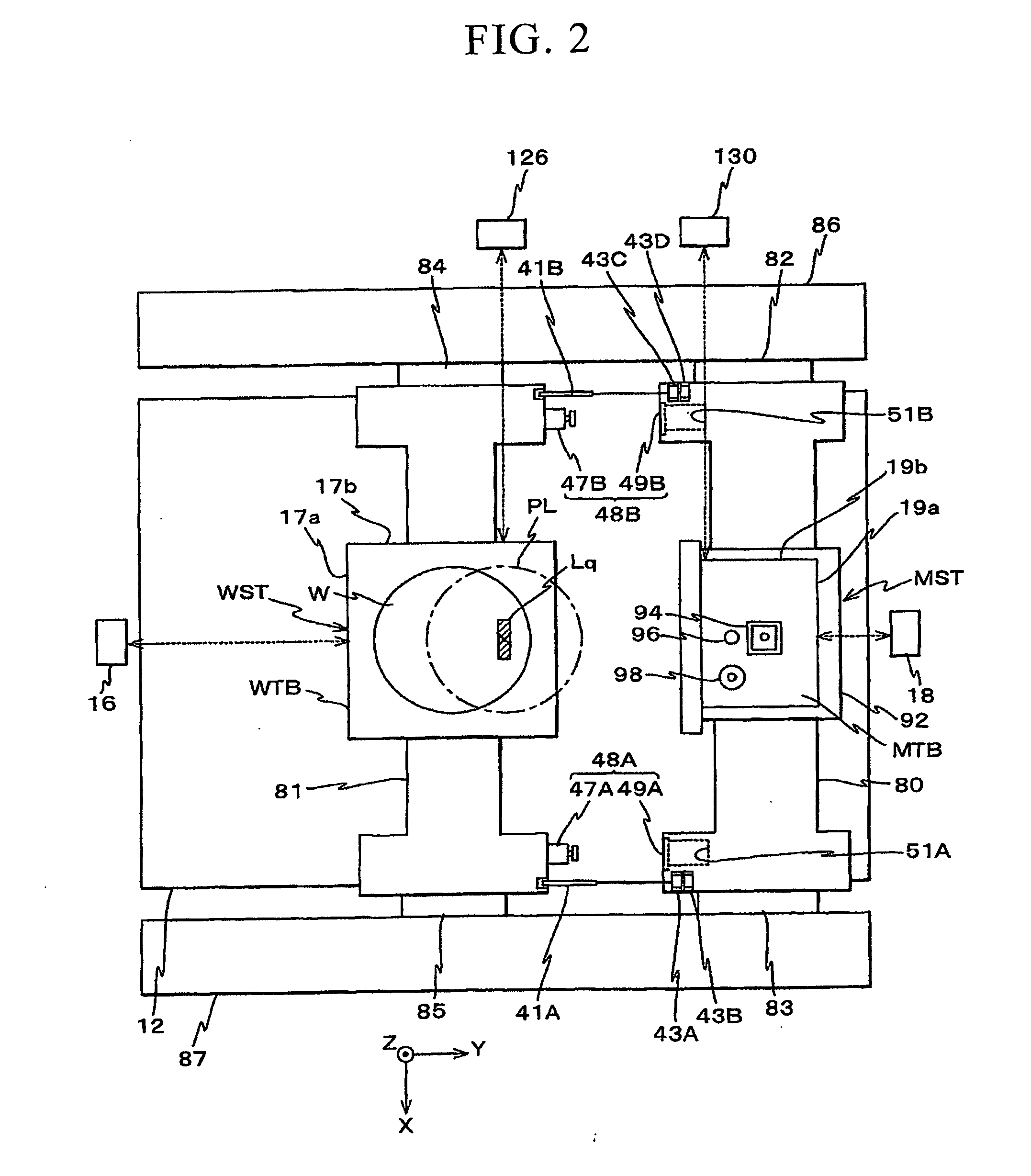
[0043]FIG. 1 schematically shows the configuration of an exposure apparatus 100 according to the present embodiment. The exposure apparatus 100 is a step-and-scan-type scanning exposure apparatus, i.e., a so-called scanner. With the present embodiment as discussed below, a projection optical system PL is provided; furthermore, in the explanation below, the Z axis lies in the directions that are parallel to an optical axis AX of the projection optical system PL, the Y axis lies in the directions within a plane that is orthogonal thereto and wherein a reticle and a wafer are scanned relative to one another, the X axis lies in the directions that are orthogonal to the Z axis and the Y axis, and the θx, the θy, and the θz directions lie in rotational (inclined) directions around the X axis, the Y axis and the Z axis, respectively.

[0044]The exposure apparatus 100 compris...

second embodiment

[0159]The following explains a second embodiment of the present invention, referencing FIG. 12. In the present embodiment, the X heads 66 and the like (FIG. 1) are not directly supported by a measurement frame, but rather are supported by a member that is engaged with the measurement frame. Constituent components in FIG. 12 that correspond to those in FIG. 1 are assigned identical or similar symbols, and detailed descriptions thereof are omitted or simplified.

[0160]FIG. 12 shows an exposure apparatus 100A of the present embodiment. In FIG. 12, instead of the measurement frame 21 in FIG. 1, a flat plate-shaped measurement frame 21M is supported via the vibration isolating members 23A, 23B and the like so that it is suspended from the suspending members 22A, 22B and the like. In addition, a base (hereinbelow, called “head base”) 26 for the flat plate-shaped encoder heads is vacuum chucked to the bottom surface of the measurement frame 21M. Numerous openings (not shown), which are for ...

third embodiment

[0173]The following explains a third embodiment of the present invention, referencing FIG. 13 through FIG. 15. In the present embodiment, the head base 26 is not coupled to the measurement frame 21M via gas bearings as in the embodiment shown in FIG. 12, but rather it is coupled more via a simpler flexural mechanism. Constituent components in FIG. 13 through FIG. 15 that are the same or similar to those in FIG. 12 are assigned the same symbols, and the explanations thereof are omitted.

[0174]FIG. 13 shows an exposure apparatus 100B of the present embodiment. In FIG. 13, the head base 26, whereto the X heads 66 and the like are fixed, is coupled to the bottom surface of the measurement frame 21M via numerous rod shaped flexural members 113, which are substantially disposed at prescribed intervals in the X directions and the Y directions, in the state wherein the head base 26 can be displaced in directions along the front surface of the plate 28 (wherein the X scales 39X1, 39X2 and the...


PUM

PropertyMeasurementUnit
wavelengthaaaaaaaaaa
refractive indexaaaaaaaaaa
wavelengthaaaaaaaaaa

Abstract

An exposure apparatus can mitigate the impact of fluctuations in the refractive index of ambient gas, and improve, for example, stage positioning accuracy. An exposure apparatus radiates an exposure illumination light to a wafer on a wafer stage through a projection optical system, and forms a prescribed pattern on the wafer, and comprises: a scale, which is provided to the wafer stage; a plurality of X heads, which detect information related to the position of the scale; a measurement frame that integrally supports the plurality of X heads and has a coefficient of linear thermal expansion that is smaller than that of the main body of the wafer stage (portions excepting a plate wherein the scale is formed); and a control apparatus that derives information related to the displacement of the wafer stage based on the detection results of the plurality of X heads.

Description

CROSS-REFERENCE TO RELATED APPLICATION[0001]This application claims priority to Japanese Patent Application No. 2007-187649, filed Jul. 18, 2007 and to U.S. provisional application No. 60 / 929,988, filed Jul. 20, 2007, the contents of which are incorporated herein by reference.BACKGROUND[0002]1. Field of the Invention[0003]The present invention relates to: a measurement technology and a stage technology that measure the position of a movable member, e.g., a stage, that is for moving an object; an exposure technology that uses the stage technology to expose the object; and a device fabrication technology that uses the exposure technology to fabricate a device, e.g., a semiconductor device or a liquid crystal display device.[0004]2. Description of Related Art[0005]Lithography for fabricating devices (electronic devices, microdevices, and the like), such as semiconductor devices and liquid crystal display devices, employs an exposure apparatus (e.g., a static exposure type—a full field ...

Claims


Application Information

Patent Timeline
Patent Type & Authority Applications(United States)
IPC IPC(8): G03B27/42G01B11/14G03B27/58
CPCG03F7/70775G03F7/70858Y10T29/49002G03F7/70341G03F7/70716G03F7/7015G01B11/00G03F7/70H01L21/027G03F7/709G03F7/70725
Inventor ARAI, DAI
Owner NIKON CORP
Why Eureka
Try Eureka