Lenticular lens medium
- Summary
- Abstract
- Description
- Claims
- Application Information
AI Technical Summary
Benefits of technology
Problems solved by technology
Method used
Image

Examples
Embodiment Construction
[0029]Preferred embodiments of the present invention will be described with reference to the accompanying drawings.
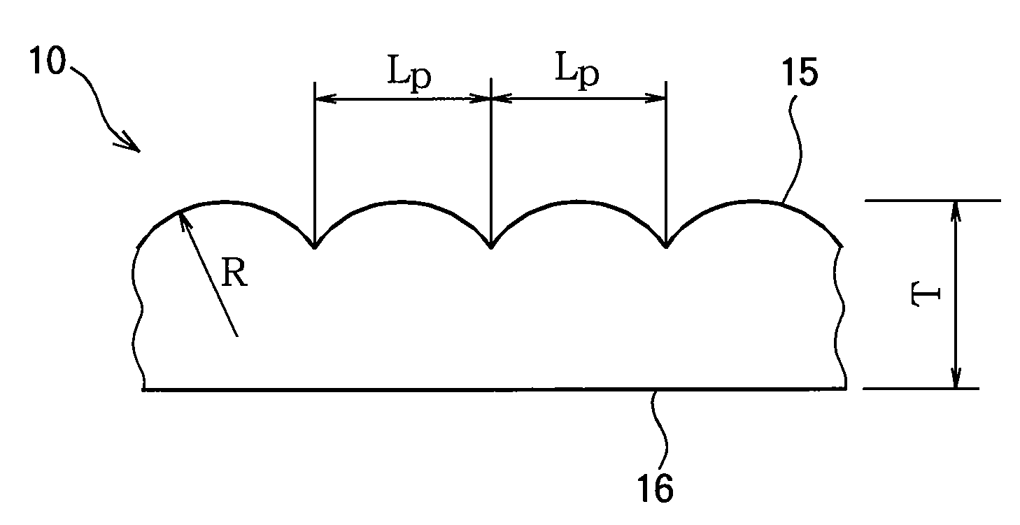
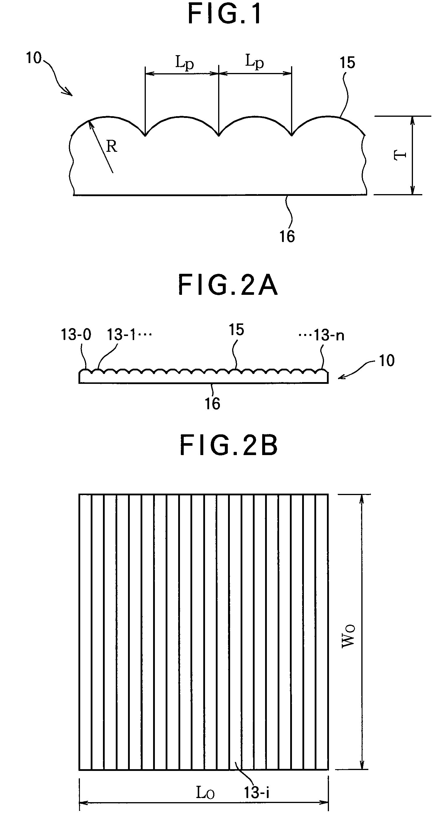
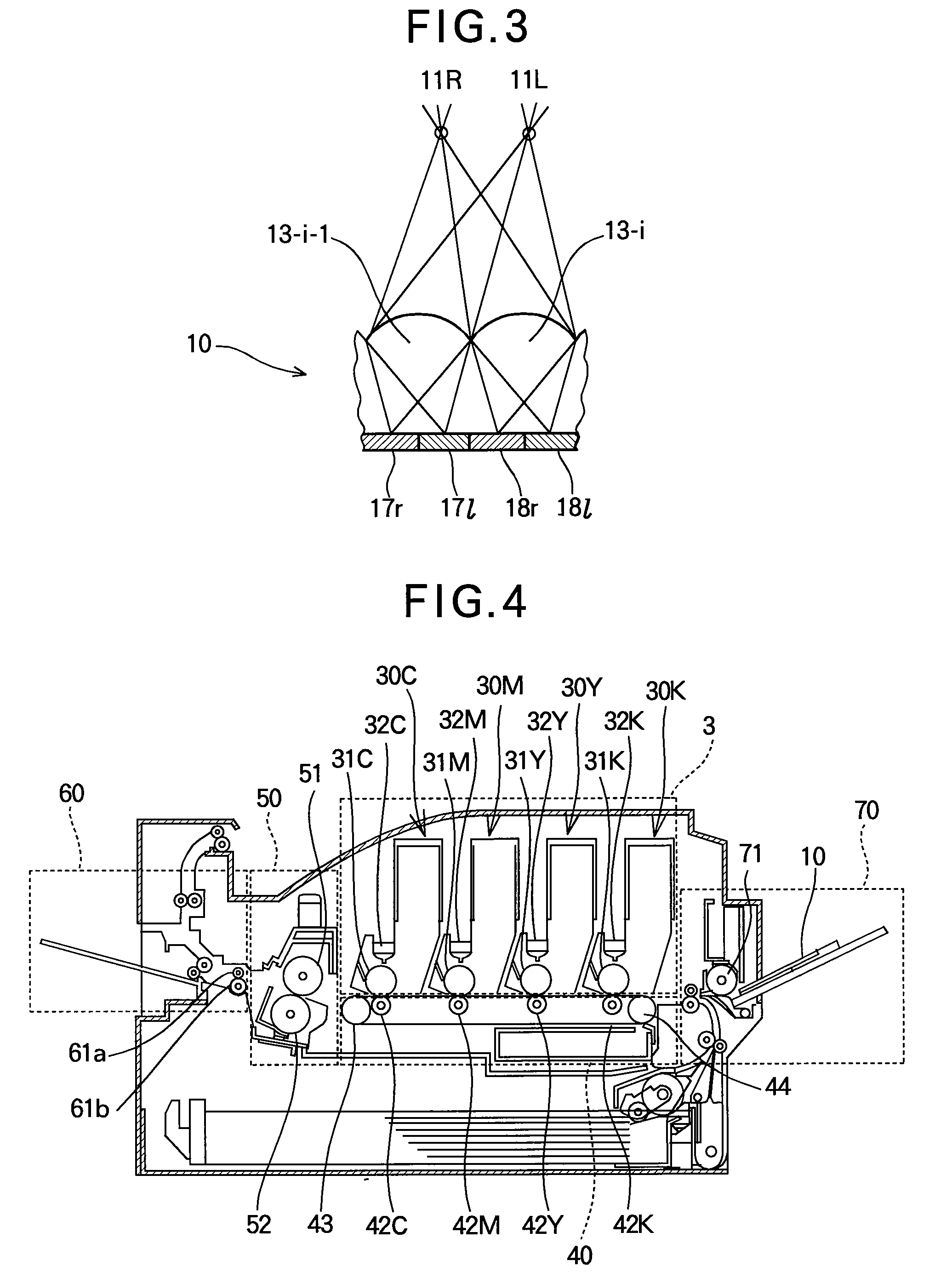
[0030]The lenticular lens medium of the present invention relates to a printing medium used in image processing systems such as copiers, facsimile machines, printers and personal computers, and used as a printing material capable of providing stereoscopic vision or motion picture of information such as characters or images. The stereoscopic vision or motion picture is obtained using various methods, for example, changing (where two or more pictures change depending on viewing angle), morphing (where one of two or more pictures is once blurred and transforms into next picture), zooming (where a picture is viewed as though the picture moves from a near position to a remote position or conversely), and animation (where a picture is viewed as a slightly different picture, or is viewed as though the picture moves). The present invention can be used in wide industrial fields ...
PUM
| Property | Measurement | Unit |
|---|---|---|
| Temperature | aaaaa | aaaaa |
| Percent by mass | aaaaa | aaaaa |
| Percent by mass | aaaaa | aaaaa |
Abstract
Description
Claims
Application Information
 - R&D
- Intellectual Property
- Life Sciences
- Materials
- Tech Scout
- Unparalleled Data Quality
- Higher Quality Content
- 60% Fewer Hallucinations
Browse by: Latest US Patents, China's latest patents, Technical Efficacy Thesaurus, Application Domain, Technology Topic, Popular Technical Reports.
© 2025 PatSnap. All rights reserved.Legal|Privacy policy|Modern Slavery Act Transparency Statement|Sitemap|About US| Contact US: help@patsnap.com