Permanent magnet motor for subsea pump drive

a permanent magnet motor and subsea pump technology, applied in the direction of positive displacement liquid engine, pump, machine/engine, etc., can solve the problems of low efficiency and low power factor, increasing the need for subsea pumps in the oil and gas industry, and reducing the service life of the pump. , to achieve the effect of preventing the corrosion of the rotor

Inactive Publication Date: 2009-09-17
GENERAL ELECTRIC CO
View PDF11 Cites 44 Cited by
  • Summary
  • Abstract
  • Description
  • Claims
  • Application Information

AI Technical Summary

Benefits of technology

[0006]According to another embodiment, a subsea pump drive system comprises a permanent magnet subsea pump drive motor having a rotor configured with a plurality of permanent magnet pole pieces, the rotor and plurality of pole pieces disposed within a non-magnetic can configured to prevent corrosion of the rotor and plurality of pole pieces.

Problems solved by technology

The need for subsea pumps in the oil and gas industry has been increasing due to increasing energy requirements, and because onshore energy sources are becoming more scarce.
Use of induction type motors has been problematic however, since induction motors are low efficiency and low power factor motors.
This low efficiency and low power factor undesirably require an oversized umbilical connection and variable frequency converter on the topside in order to provide a large amount of VAR power to the subsea motor.
Both, the oversized umbilical connection and variable frequency converter undesirably increase the cost to the subsea pumping system.

Method used


Image

  • Permanent magnet motor for subsea pump drive
  • Permanent magnet motor for subsea pump drive
  • Permanent magnet motor for subsea pump drive

Examples


Embodiment Construction

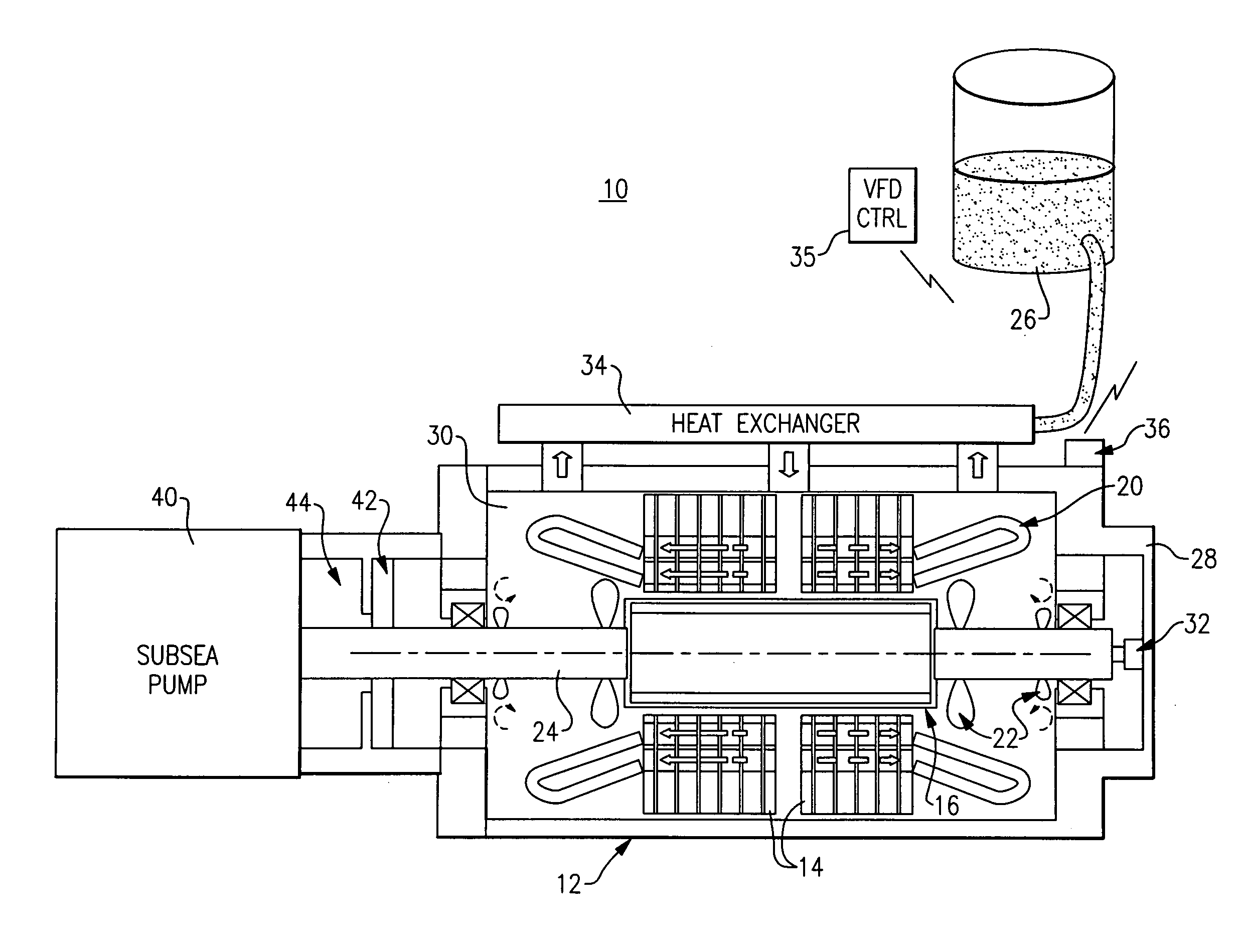
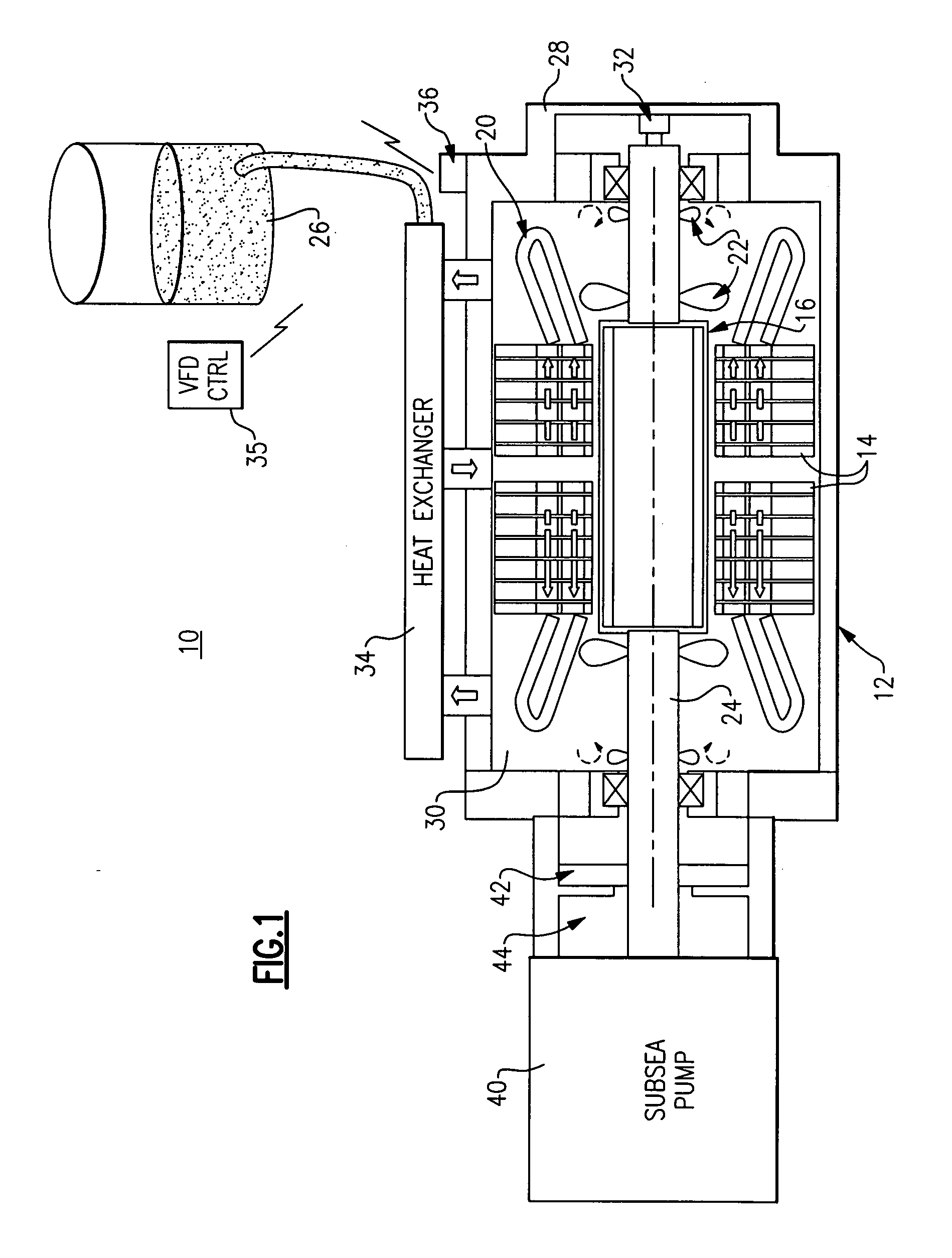
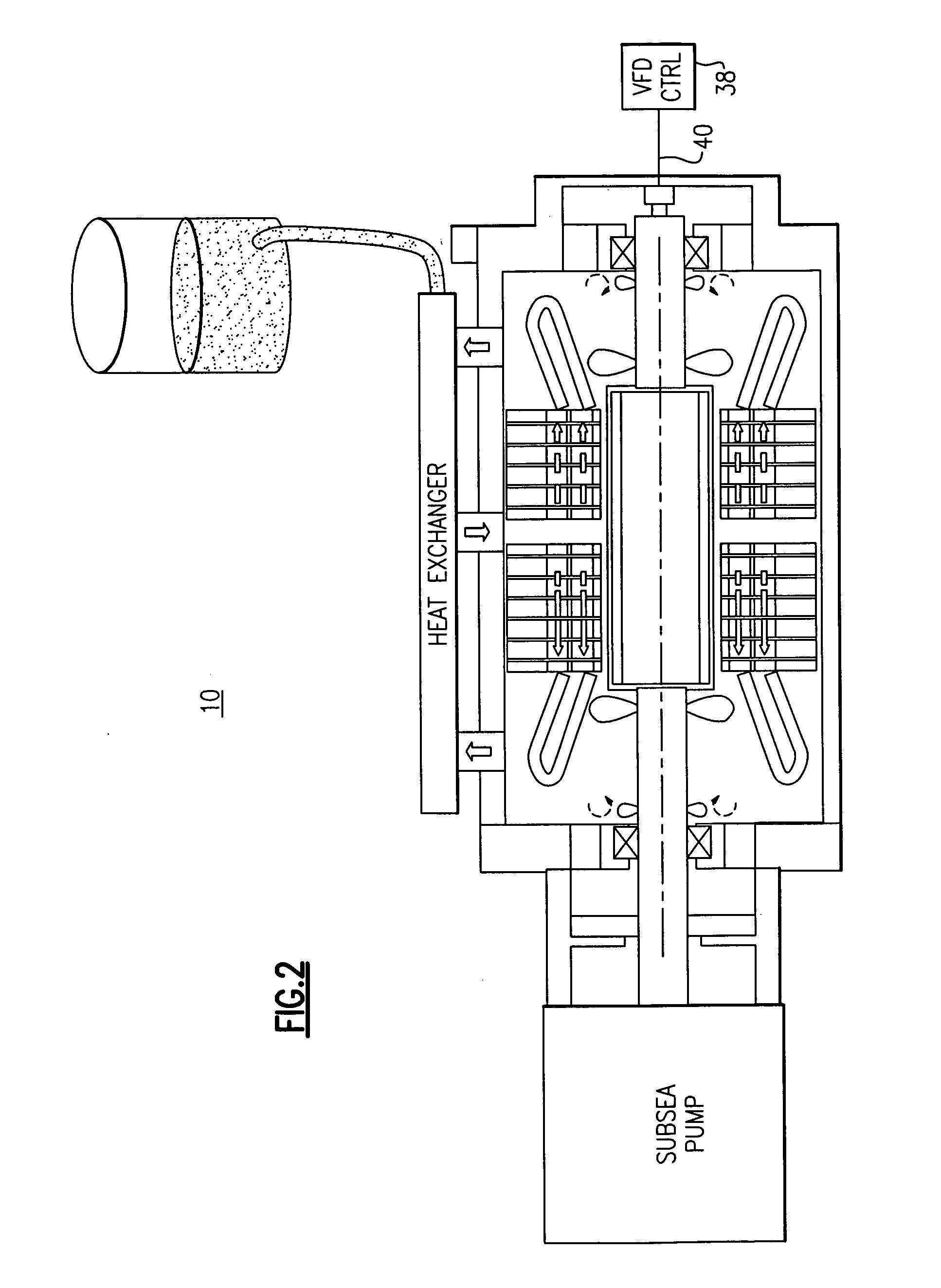
[0018]FIG. 1 illustrates a permanent magnet motor subsea pump drive 10 according to one embodiment of the invention. Subsea pump drive 10 includes a permanent magnet motor 12 comprising a stator 14 and a rotor 16. Windings 20 are disposed in stator slots. The rotor 16 comprises a plurality of permanent magnet (PM) poles described herein below with reference to FIGS. 3 and 4. The rotor 16 also includes a non-magnetic can configured to fix the permanent magnets to the rotor 16, also described further herein below with reference to FIG. 3.

[0019]Four sets of blades 22 are disposed on the rotor shaft 24. These blades 22 are configured to pump cooling fluid 26 flowing through a motor sealing can 28 that encapsulates both the stator 14 and the rotor 16 according to one aspect of the invention illustrated in FIGS. 5 and 6, where both the stator 14 and the rotor 16 are canned for corrosion protection when processed fluid is used for cooling. The cooling fluid 26 works to provide cooling of t...


PUM


Abstract

A subsea pump drive employs a permanent magnet (PM) motor to drive a subsea pump. The PM motor rotor in one embodiment is canned with a non-magnetic material such as inconel that can provide a desired level of corrosion protection. The PM motor provides a subsea pump drive that is smaller and more efficient, having a high power factor than a subsea pump drive utilizing a conventional induction motor. The PM motor subsea pump drive eliminates the necessity for a topside storage tank and associated fluid transfer lines when the motor rotor is cooled with processed fluid.

Description

BACKGROUND[0001]The invention relates generally to subsea pumping systems and methods, and more specifically a canned permanent magnet motor for a subsea pump drive.[0002]The need for subsea pumps in the oil and gas industry has been increasing due to increasing energy requirements, and because onshore energy sources are becoming more scarce. These industries must now look for energy sources offshore; and the distance between shore and subsea fields continues to increase.[0003]Electrical motors have been selected as a standard to drive the subsea pumps due to ease of power transfer over long distances when compared to other drive systems and methods, including, for example, hydraulic driven pumps. Conventional systems and methods employ induction motors for driving the aforesaid subsea pumps. Use of induction type motors has been problematic however, since induction motors are low efficiency and low power factor motors. This low efficiency and low power factor undesirably require an...

Claims


Application Information

Patent Timeline
Patent Type & Authority Applications(United States)
IPC IPC(8): F04B49/00H02K9/00F04B17/03
CPCH02K5/1285H02K9/193H02K9/19
Inventor QU, RONGHAIKOTHNUR, VASANTH KUMAR SRINIVASAHUANG, XIANGHUI
Owner GENERAL ELECTRIC CO
Why Eureka
Try Eureka