Dual-conductor welding gun

Inactive Publication Date: 2009-09-24
MORENO GOZALBO JOSE CARLOS
View PDF5 Cites 46 Cited by
  • Summary
  • Abstract
  • Description
  • Claims
  • Application Information

AI Technical Summary

Benefits of technology

[0001]The present welding gun with double conductor consists of a specific industrial electric peg for its connection to an electrical energy converter, a bundle of conductors inside an insulated hose, a

Problems solved by technology

Nowadays, both in manual and automated industrial welding, failure of the intensity conductor causes production losses, and when such failure occurs during periods with no human monitoring, the welding process stops at that point u

Method used


Image

  • Dual-conductor welding gun
  • Dual-conductor welding gun

Examples


Embodiment Construction

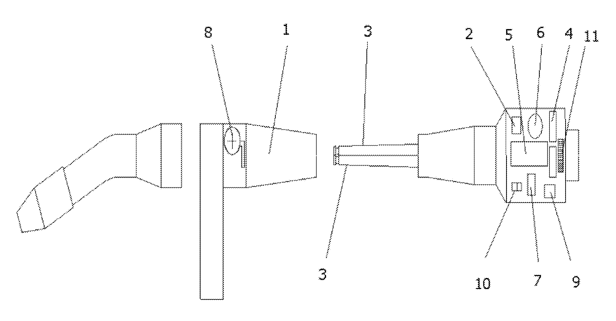
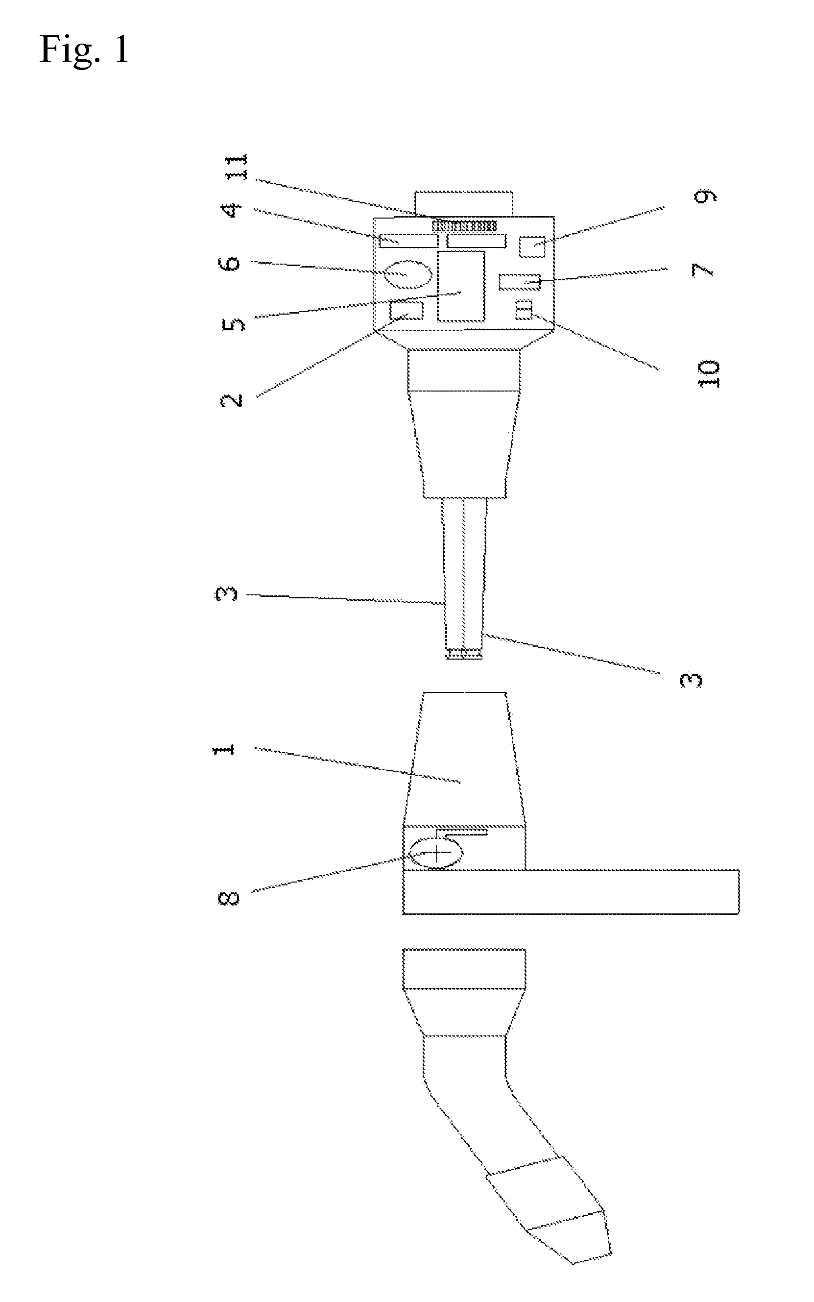
[0004]This gun or torch is designed to be connected to a direct current power supply system with a voltage between 10 and 40 Volts and an intensity between 1 and 400 Amperes, with a maximum allowed intensity of 500 Å.

[0005]The author of the present invention proposes a solution to the problem previously described by using two conductors. The failure of one of the conductors will trigger an alarm that can be used to voluntarily stop the process and / or continue with it under similar working conditions, since each conductor is capable to withstand on its own the current intensity needed for normal operating conditions.

[0006]Both conductors originate at the same contact in the peg, run in parallel through separate conducts that can be cooled or not, and, when reaching the gun (torch), they meet again to provide full intensity at the welding tip. The advantage of this solution is that, if the same amount of copper is used and the conductor is divided in two equal parts, the total surface...


PUM

PropertyMeasurementUnit
Frequencyaaaaaaaaaa
Temperatureaaaaaaaaaa
Polarityaaaaaaaaaa

Abstract

Welding gun with double conductor composed by a torch body (1) and electronic scales (2) to measure the intensity of the sensors (6) located in each conductor (3) and with mechanisms to trigger an alarm when there is an imbalance of the intensities circulating through both conductors. To this end, a microcontroller (5) connected to intensity (6) and temperature (8) sensors in the conductors is used, with indicators of failure or anomaly. The microcontroller (5) program calculates the difference between the magnitudes of both intensity signals and determines which of the two is higher, and, based on predefined parameters, triggers the corresponding alarm signal.

Description

PURPOSE OF THE INVENTION[0001]The present welding gun with double conductor consists of a specific industrial electric peg for its connection to an electrical energy converter, a bundle of conductors inside an insulated hose, and a welding gun (also called “torch”) whose tip is used for welding, everything arrayed in such a way that an alarm letting the process control system know if the conductors have failed can be triggered.[0002]Its application field is the industry aimed at industrial welding.BACKGROUND OF THE INVENTION[0003]Nowadays, both in manual and automated industrial welding, failure of the intensity conductor causes production losses, and when such failure occurs during periods with no human monitoring, the welding process stops at that point until the problem is solved, which generates production chain position adjustment costs. Failure can be due to different causes such as degradation by corrosion of the conductive material, breaking by mechanical wear, or overheatin...

Claims


Application Information

Patent Timeline
IPC IPC(8): B23K9/00
CPCB23K9/0956B23K9/28H05H2001/3494H05H1/36H05H2001/3473B23K9/323H05H1/3473H05H1/3494B23K9/00B23K9/095B23K9/1056H05B7/11B23K37/0258Y10S29/013
Inventor MORENO GOZALBO, JOSE CARLOS
Owner MORENO GOZALBO JOSE CARLOS
Why Eureka
Try Eureka