Switching power supply

a power supply and power supply technology, applied in the direction of electric variable regulation, process and machine control, instruments, etc., can solve the problems of failure of ic and such electronic components in the load, the output voltage cannot be controlled in fig. 7, and the load cannot be controlled. the effect of preventing the output voltage from falling and reducing the rapid increase of the load curren

Inactive Publication Date: 2009-09-24
FUJI ELECTRIC CO LTD
View PDF7 Cites 8 Cited by
  • Summary
  • Abstract
  • Description
  • Claims
  • Application Information

AI Technical Summary

Benefits of technology

[0029]According to the invention, the first reference voltage value for stopping the switching operation and the second reference voltage value for stopping the electric power feed to the PWM control circuit are set individually. According to the invention, the second reference voltage value is set to be lower than the first reference voltage value. The reference voltage setting described above makes the PWM control circuit resume the switching operation thereof quickly even when the load current increases rapidly in the OFF-state of the PWM control circuit. Therefore, the output voltage is prevented from falling. Further, the output voltage ringing caused in the conventional switching power supply in association with the rapid increase of the load current is reduced by the switching power supply according to the invention.

Problems solved by technology

However, it is impossible for the PWM control circuit in FIG. 7 to resume (start) the switching operation immediately after the operation power is fed thereto.
Moreover, the output voltage will cause ringing due to the reasons described later after the PWM control circuit resumes the switching operation.
The greatly changing voltage affects the IC and such electronic component parts in the load adversely, causing malfunctions of the IC and such electronic component parts in the load.
However, operation power supply voltage Vref is not stabilized so soon at a certain voltage.

Method used


Image

  • Switching power supply
  • Switching power supply
  • Switching power supply

Examples


first embodiment

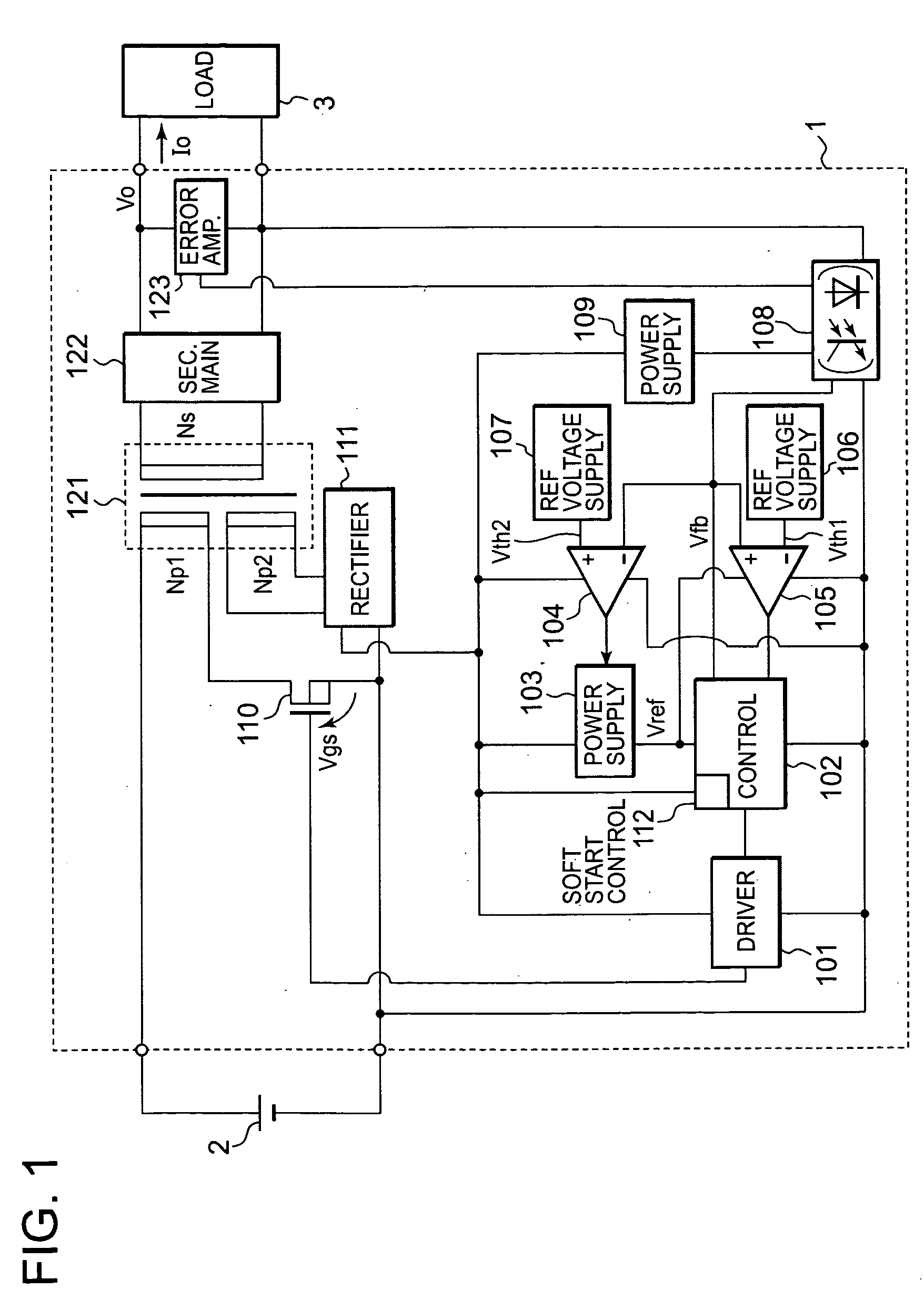
[0040]FIG. 1 is a block diagram of a switching power supply according to the invention. The same reference numerals as used in FIG. 7 are used to designate the same constituent elements and their duplicated descriptions are omitted for the sake of simplicity.

[0041]The switching power supply shown in FIG. 1 includes second power supply circuit 109 and second reference voltage supply 107 added to the constituent elements of the switching power supply shown in FIG. 7. In the switching power supply shown in FIG. 1, a path, through which a result of comparison is transferred from second comparator 104 to first power supply circuit 103, is added. The switching power supply shown in FIG. 1 is different from the conventional switching power supply shown in FIG. 7 also in that a current is fed from second power supply circuit 109 to photocoupler 108.

[0042]The switching power supply shown in FIG. 1 is configured such that the operation power of soft start control circuit 112 in PWM control ci...

second embodiment

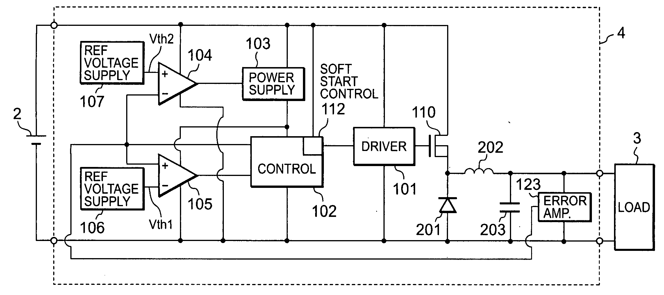
[0056]FIG. 4 is a block diagram of a switching power supply according to the invention. The non-isolated_switching power supply shown in FIG. 4 realizes the same operations same with the operations conducted by the switching power supply shown in FIG. 1. The same reference numerals as used in FIG. 1 are used to designate the same constituent elements in FIG. 4 and their duplicated descriptions are omitted for the sake of simplicity.

[0057]Photocoupler 108, second power supply circuit 109, rectifier circuit 111, transformer 121, and secondary-side main circuit 122 shown in FIG. 1 are not included in switching power supply 4 shown in FIG. 4. Switching power supply 4 shown in FIG. 4 includes a main circuit formed of diode 201, inductor 202 and capacitor 203 added thereto. Switching power supply 4 according to the second embodiment forms a non-isolated_DC-DC converter.

[0058]Although operation power is fed from input power supply 2 to second comparator 104, first power supply circuit 103 ...

third embodiment

[0065]FIG. 5 is a block diagram of a switching power supply according to the invention. The switching power supply shown in FIG. 5 is a modification of the switching power supply shown in FIG. 1.

[0066]As shown in FIG. 5, rectifier circuit 111 shown in FIG. 1 is omitted and DC power supply 141 is employed in substitution for rectifier circuit 111. DC power supply 141 is employed for a control power supply. The configuration described above prevents the problems as described in the paragraph [0019] from causing and facilitates omitting second power supply circuit 109.

[0067]When the voltage of input power supply 2 is as high as to be employable for the control power without boosting nor bucking, rectifier circuit 111 and second power supply circuit 109 may be omitted by employing the structure, in which the power from input power supply 2 is used directly for control power.


PUM


Abstract

A switching power supply, which operates intermittently under a light load for suppressing electric power consumption, reduces output voltage variations caused when a load current increases rapidly from a light load state, and reduces output voltage ringing. The switching power supply includes a comparator that compares a feedback signal obtained by isolating the output from an error amplifier with a burst threshold value and a comparator that compares the feedback signal with a power-supply-interruption threshold value preset to be lower than the burst threshold value. The switching power supply stops output of a driving pulse from a driver circuit when the feedback signal is lower than the burst threshold value. The switching power supply also stops the output of operation power from first power supply circuit when the feedback signal is lower than the power-supply-interruption threshold value.

Description

FIELD OF THE INVENTION[0001]The invention relates to a switching power supply that operates intermittently under a light load and stops the operation of the control circuit during a period during which switching is stopped for reducing the power consumption therein.BACKGROUND[0002]It has been required for the switching power supply apparatuses to exhibit a high conversion efficiency, to cause less noise, to be small in size, to be manufactured with less manufacturing costs, and to be very reliable. To meet these requirements, various circuit configurations have been proposed.[0003]FIG. 7 is a block diagram of a conventional switching power supply. The switching power supply shown in FIG. 7 is equivalent to the switching power supply described in FIG. 4 in Japanese Unexamined Patent Application Publication No. 2005-006386 (FIG. 4 and the description with reference to FIG. 4).[0004]Referring now to FIG. 7, switching power supply 1 generates, from the DC output of input power supply 2,...

Claims


Application Information

Patent Timeline
Patent Type & Authority Applications(United States)
IPC IPC(8): G05F1/10
CPCH02M1/36Y02B70/16H02M2001/0032H02M3/156Y02B70/10H02M1/0032
Inventor YAMADA, MICHIYANISHIKAWA, YUKIHIRO
Owner FUJI ELECTRIC CO LTD
Why Eureka
Try Eureka