Targeting apparatus connecting to locking nails for the correction and fixation of femur deformity of a child

a technology for fixing devices and femurs, which is applied in the field of targeting apparatus for fixing femur deformities, can solve the problems of inability to reliably fasten the blade b>52/b> in the femoral neck, loss of correction, and malunion, and achieves the effects of less muscle, less cutting, and relatively small torque of locking nails

Inactive Publication Date: 2009-09-24
CHANG GUNG MEMORIAL HOSPITAL
View PDF4 Cites 34 Cited by
  • Summary
  • Abstract
  • Description
  • Claims
  • Application Information

AI Technical Summary

Benefits of technology

[0007]It is therefore one object of the invention to provide a targeting apparatus operatively connecting to locking nails for the correction of the deformity in proximal femur of a child. The invention has the advantages as detailed below. The femoral shaft is fixed by three cortical bones and thus is more reliable as compared with the conventional angled blade plate. Wound on femur has a lesser area and cut muscle is less. Torque of the locking nails is relatively small and thus is better than the conventional angled blade plate. A doctor can use first and second locking nails to fix the femoral osteotomy in a labor saving manner. The leg only has a small bulging and no blade plate is disposed between the skin and the bone after surgery. The locking nails are inserted into positions below the femoral head and thus cause no injury to the body and do not hinder blood circulation.

Problems solved by technology

The resulting loss of correction, malunion, nonunion, and prolonged immobilization are major surgical complications.
Besides, a big wound and massive muscle dissection are required to implant the plate.
However, the fastening of the blade 52 in the femoral neck is not reliable.
Thus, time required for healing the femoral osteotomy may be prolonged undesirably.
Moreover, the positioning of the angled blade plate 50 may cause a great pain to the leg.
In addition, the angled blade plate 50 can cause bulging to the leg after surgery.

Method used


Image

  • Targeting apparatus connecting to locking nails for the correction and fixation of femur deformity of a child
  • Targeting apparatus connecting to locking nails for the correction and fixation of femur deformity of a child
  • Targeting apparatus connecting to locking nails for the correction and fixation of femur deformity of a child

Examples


Embodiment Construction

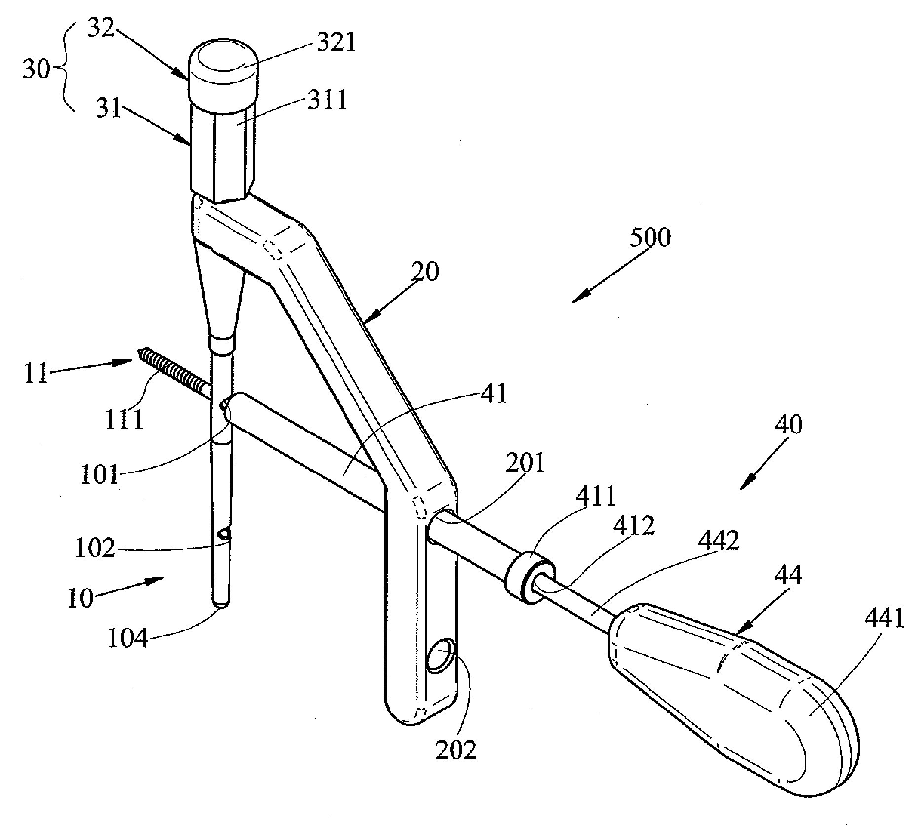
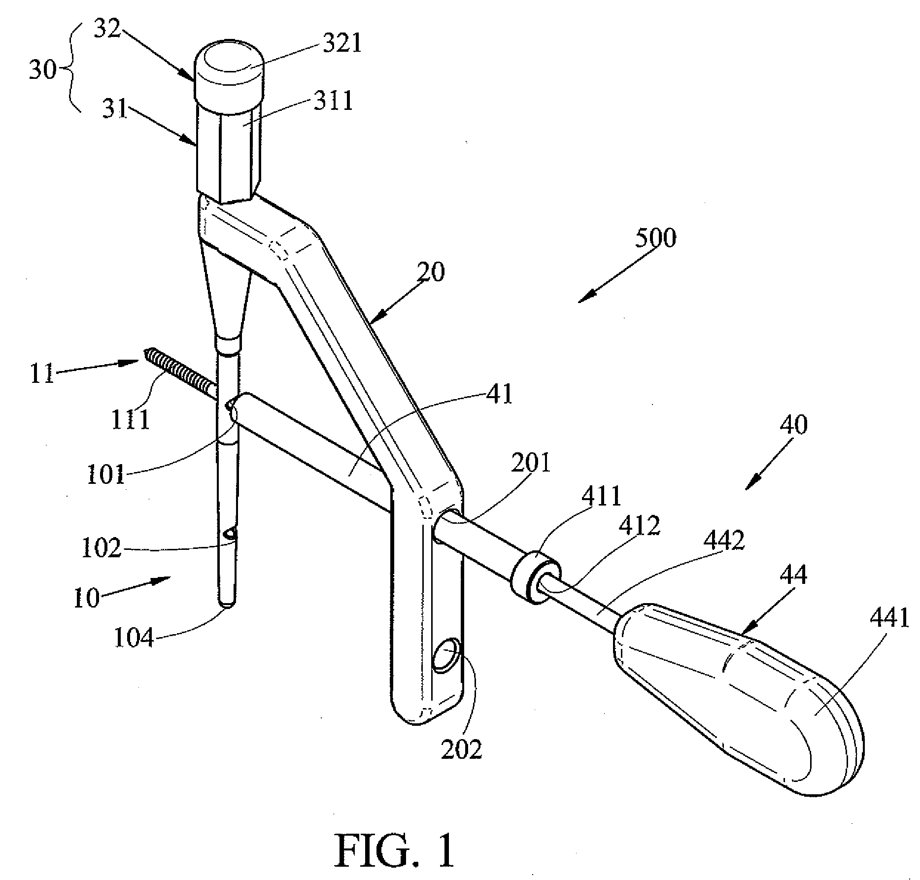
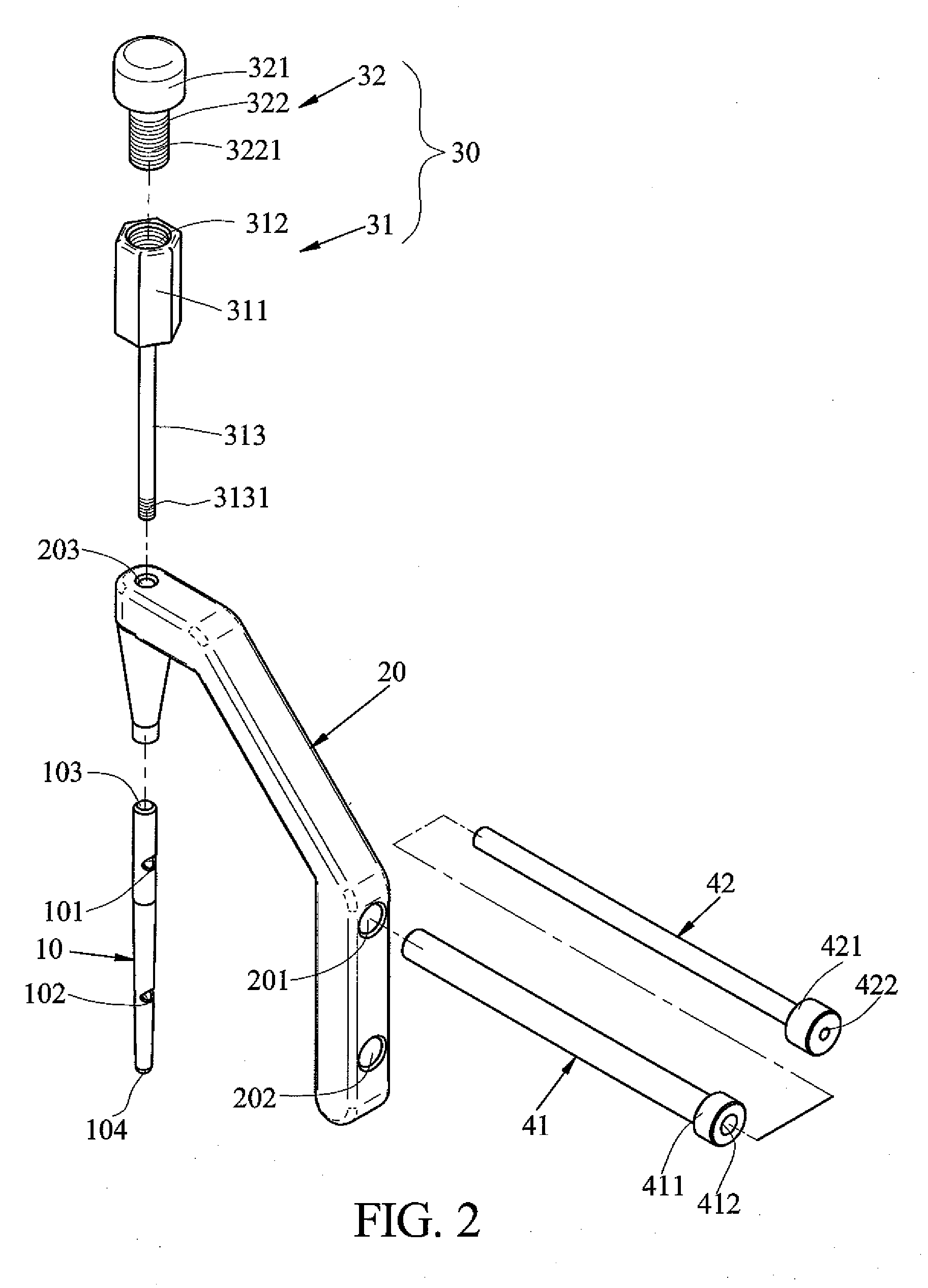
[0016]Referring to FIGS. 1 to 5, a targeting apparatus 500 for the correction of the deformity in proximal femur of a child in accordance with a preferred embodiment of the invention is shown. The targeting apparatus 500 operates in cooperation with a nail assembly (not numbered) which comprises the following components.

[0017]A nail retention member 10 is cylindrical. The nail retention member 10 is tapered toward its bottom end 104 which is half-spherical. The nail retention member 10 has an upper through hole 101, a lower through hole 102, and a top cavity 103 having inner threads.

[0018]A first locking nail 11 has a forward threaded portion 111, an enlarged head 112, and a recess 113 in the head 112.

[0019]A second locking nail 12 has a forward threaded portion 121, an enlarged head 122, and a recess (not numbered) in the head 122.

[0020]Preferably, the first locking nail 11 is a cannulated screw, and the second locking nail 12 is a cortical screw. Also, the first locking nail 11 ha...


PUM


Abstract

A targeting apparatus for the correction of the deformity in proximal femur of a child is disclosed and includes a retention assembly; a cylindrical nail retention member tapered toward its half-spherical bottom end and including an upper through hole, a lower through hole, and a top cavity having inner threads for releasably secured to the retention assembly; a first locking nail including a forward threaded portion, an enlarged head, and a retaining recess in the head thereof; and a second locking nail including a forward threaded portion, an enlarged head, and a retaining recess in the head thereof. The invention has the advantages of reducing the area of wound when implanting the locking nails in the femur and saving labor during surgery.

Description

BACKGROUND OF THE INVENTION[0001]1. Field of Invention[0002]The invention relates to devices for correcting and fixing tubular bones, and more particularly to an improved targeting apparatus operatively connecting to locking nails for the correction of the deformity in proximal femur of a child.[0003]2. Description of Related Art[0004]Femoral varus osteotomy is one of the most common operations of children's hips to correct the dysplasia and deformity from neuromuscular disease, developmental dysplasia of the hip, Perthes' disease, trauma and infection. The surgical procedures include osteotomy at femoral intertrochanteric area, varus deformation of femoral neck, and internal fixation by implants. The universal implant in varus osteotomy is angled blade plate in which the femoral neck is fixed by one smooth blade. However, blade loosening from the cancelleous bone in femoral neck is not uncommon. The resulting loss of correction, malunion, nonunion, and prolonged immobilization are ...

Claims


Application Information

Patent Timeline
Patent Type & Authority Applications(United States)
IPC IPC(8): A61B17/58
CPCA61B17/1725A61B17/746A61B17/744A61B17/1742
Inventor CHANG, CHIA HSIEH
Owner CHANG GUNG MEMORIAL HOSPITAL
Why Eureka
Try Eureka