External system for robotic accuracy enhancement

a technology of robotic accuracy and external system, applied in the field of robotic and equipment accuracy enhancement and methods, can solve the problems of reducing accuracy, and affecting the accuracy of robots during actual work cycles, so as to reduce or eliminate, reduce the cost of motion platforms, and tighten the tolerance of pos

Inactive Publication Date: 2009-09-24
VARIATION REDUCTION SOLUTIONS
View PDF36 Cites 88 Cited by
  • Summary
  • Abstract
  • Description
  • Claims
  • Application Information

AI Technical Summary

Benefits of technology

[0015]Another advantage of the present invention is to provide the system at a low price, which is significantly cheaper on a per robot basis than prior art systems.
[0016]Still another advantage of the present invention is to provide the system that serves as a process monitoring tool, since the EOAT pose of the motion device is actually measured at each work position, instead of simply being estimated / predicted as per many existing ‘passive’ robot accuracy enhancement packages. Such a system can be used to archive pose data during a process for later analysis.
[0017]Still another advantage of the present invention is to provide the system that significantly reduces or eliminates the need to perform in-situ calibrations or characterizations of motion platforms in an effort to ‘model’ or ‘characterize’ the motion device. Since this is an active measurement system, the proposed system may result in cheaper motion platforms being able to achieve tighter pose tolerances. An example would be the ability to replace expensive NC machines with cheaper industrial robots.
[0018]Since the proposed system has the capability to monitor the pose of the EOAT in real time, an avenue for tracking / correcting the pose of the EOAT while it performs its work (such as drilling) is made possible. Since the actual pose of the EOAT is measured, backlash can be overcome when the motion device's pose is corrected since the motion device may not be allowed to commence work until an ‘acceptable’ pose is achieved.
[0019]Still another advantage of the present invention is to provide the system that takes a ‘black-box’ approach to robot accuracy enhancement, in effect measuring the aggregate result of all the contributing factors to robot pose error without regard to implicitly measuring or modeling any individual contributor. For example, temperature effects, both ambient and internal to the motion device (such as servo temperature), are automatically accounted for via the system. Deflection is also accounted for via the system (think of the extra modeling necessary when a robot is mounted to additional slide units). Even non-geometric effects that are not usually included in a robot's kinematic modeling such as joint flexibility, link flexibility, and gear transmission error are actively accounted for in such a system. Robot or end effector wear can also be tracked over thousands of duty cycles utilizing such a system.
[0020]Still another advantage of the present invention is the ability to link together or update various coordinate frames by placing the active targets on the workpiece, fixed about the work cell, on a movable device such as a tripod, or on palletized systems. This ability allows for a multitude of capabilities, such as generating part-to-world transforms, compensating for temperature drift within a work cell, initially calibrating beacon-to-world poses, subsequently recalibrating beacon-to-world poses, or establishing the relationship between a fixed work cell and a palletized robotic system that moves to it, or even monitoring of automated guided vehicle (AGV) systems.

Problems solved by technology

Such off-line calibration methods only provide a snap-shot in time of the robot's characteristics, and do not account for the degradation in accuracy due to wear or possible thermal changes that inevitably occur in between system calibrations.
At least one from this class of methods does involve measuring the robot end effector position in the ‘work volume’ of the robot, but does not accomplish this during the robot's actual work cycle.
Each type of system is prohibitively expensive and slow for widespread application in real-time active robotic correction.
There are several limitations for solutions of this sort.
Since the apex angles between the LEDs are quite small as viewed by the camera, any error in determining the transverse position of the LEDs contributes to angular errors in the 6-DOF solution.
Similar angular ambiguity results from the distance between the photosensitive device and the corner cube being so small; any error in calculating the position of the laser spot on the photosensitive surface results in a large angular error of the target itself owing to the need for keeping the target's dimensions small enough to fit on a robot end effector.
Additionally, this grey-scale option is quite expensive, and the probe is too large and directionally-limited to be mounted on many robotic end effectors, especially where the process requires that the robot exercises a full range of poses.
Still, this target has angular limitations for yaw, pitch, and roll detection; lacks the requisite accuracy for higher-precision robot correction applications; is still too large to incorporate into many end-effector designs; and is expensive.
The probes described here are generally too large to be positioned close to the tool center point (TCP) of the robot, resulting in ‘lever-arm’ effects when ascertaining the pose of the TCP.
And, coupled with the fact that they require a laser tracker or camera-enhanced laser tracker to perform, such systems are prohibitively expensive, especially when compared to the base price of a standard articulated arm robot.
Indoor optical GPS has recently made inroads to many manufacturing solutions and can provide the current pose of a robot, but such systems cannot at this time demonstrate accuracies near those that are needed for high precision robot guidance applications.
In the context of high precision robot guidance, the cost-effectiveness of indoor GPS can only be realized when large numbers of receivers are required on the manufacturing floor.
First off, the volume of interest of ‘single sensor housing’ photogrammetric solutions is limited to a wedge that typically extends only to 6 meters from the device (the closer you get to the sensor, the smaller the transverse field of view becomes).
Since the allowable spacing between the LED targets that need to be placed on a typical robot end effector is usually small, poor apex angles generally result between the LEDs as viewed by the system.
In an effort to put all the photosensitive devices and optics in a single sensor housing, the apex angles between each line of sight are likewise compromised.
The poor apex angles could be corrected by adding another photogrammetric head in the work cell at nearly 90 degrees to the first photogrammetric head, but the resulting overlap between the two wedge volumes becomes prohibitively small for most applications.
Taking into consideration that a single head photogrammetric system typically costs as much as a laser tracker, the cost per measurement volume becomes a huge factor.
Again, though, the volume of overlap between the cameras is limited.
And, while the sensors for these types of photogrammetric systems are cheaper than the ‘single sensor housing’ varieties, they are still considerable when compared to the cost of a robot, so adding additional LOS capability by adding more sensors is seldom a viable option.
As a stand-alone gimbal, such systems cannot provide accuracies greater than those already achieved by robots with enhanced accuracy modeling.
Even if the ranging capability was not used in favor of locating the angular positions of 3+reflectors on a robot EOAT and solving 6-DOF via traditional photogrammetric techniques, one again arrives at a poor apex-angle solution.
Stereo-triangulation is undesirable since it requires a minimum of two tracking systems and it is a static measuring technique.
Similarly, imaging by camera is undesirable since the resolution of the system is typically much too low to adequately cover the working envelope of a robot, in addition to the unrealistic stabilities and accuracies required when generating / maintaining the internal calibrations of such optical systems.

Method used


Image

  • External system for robotic accuracy enhancement
  • External system for robotic accuracy enhancement
  • External system for robotic accuracy enhancement

Examples


Embodiment Construction

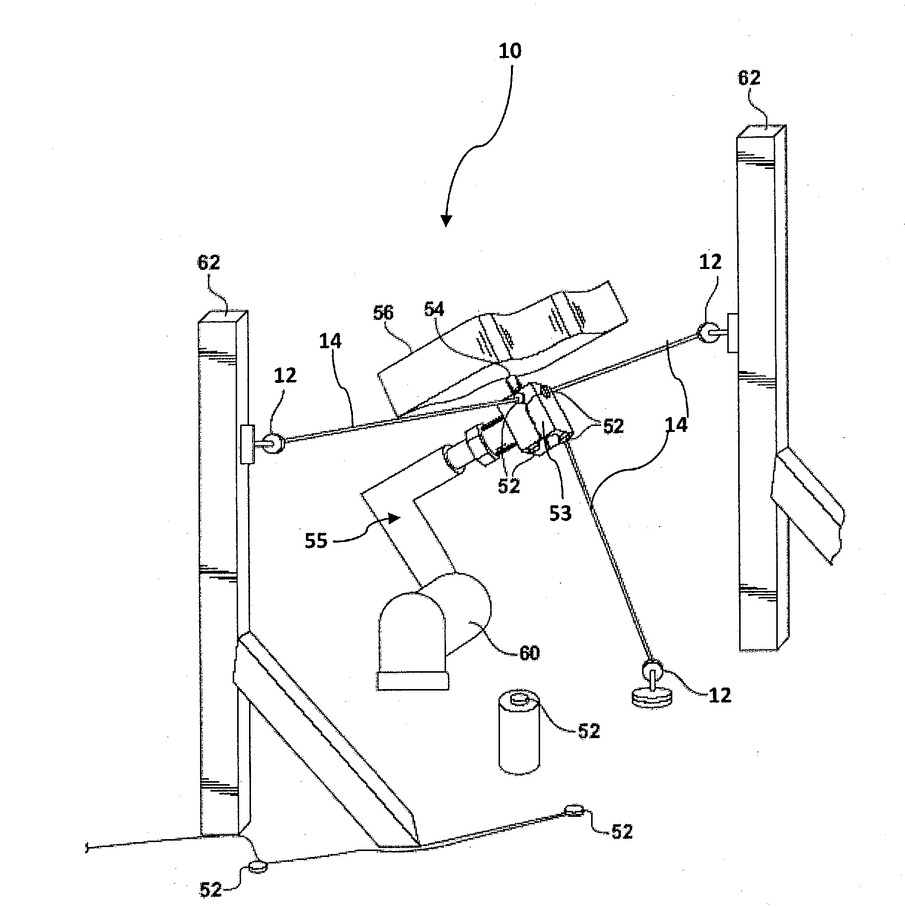
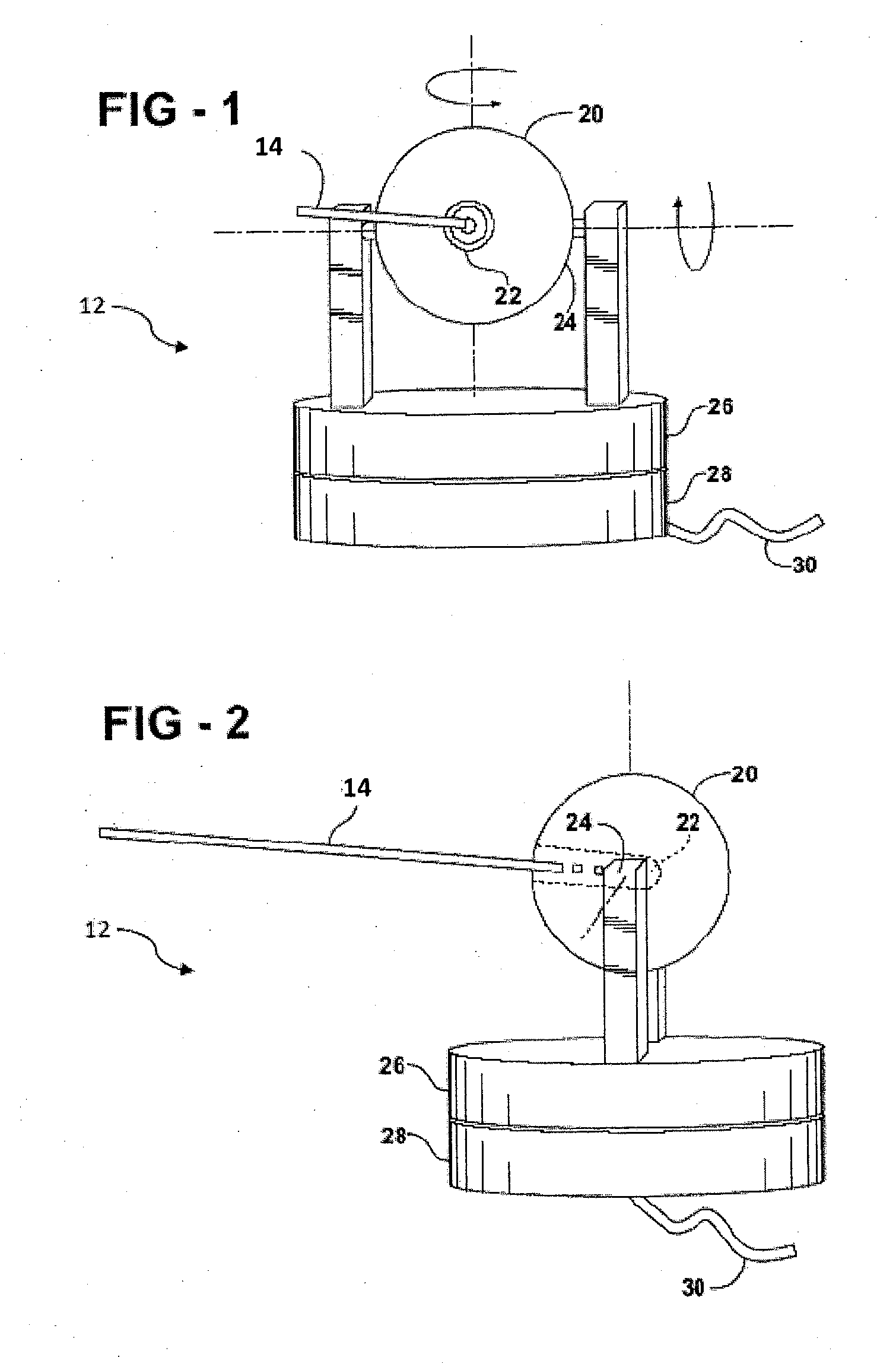
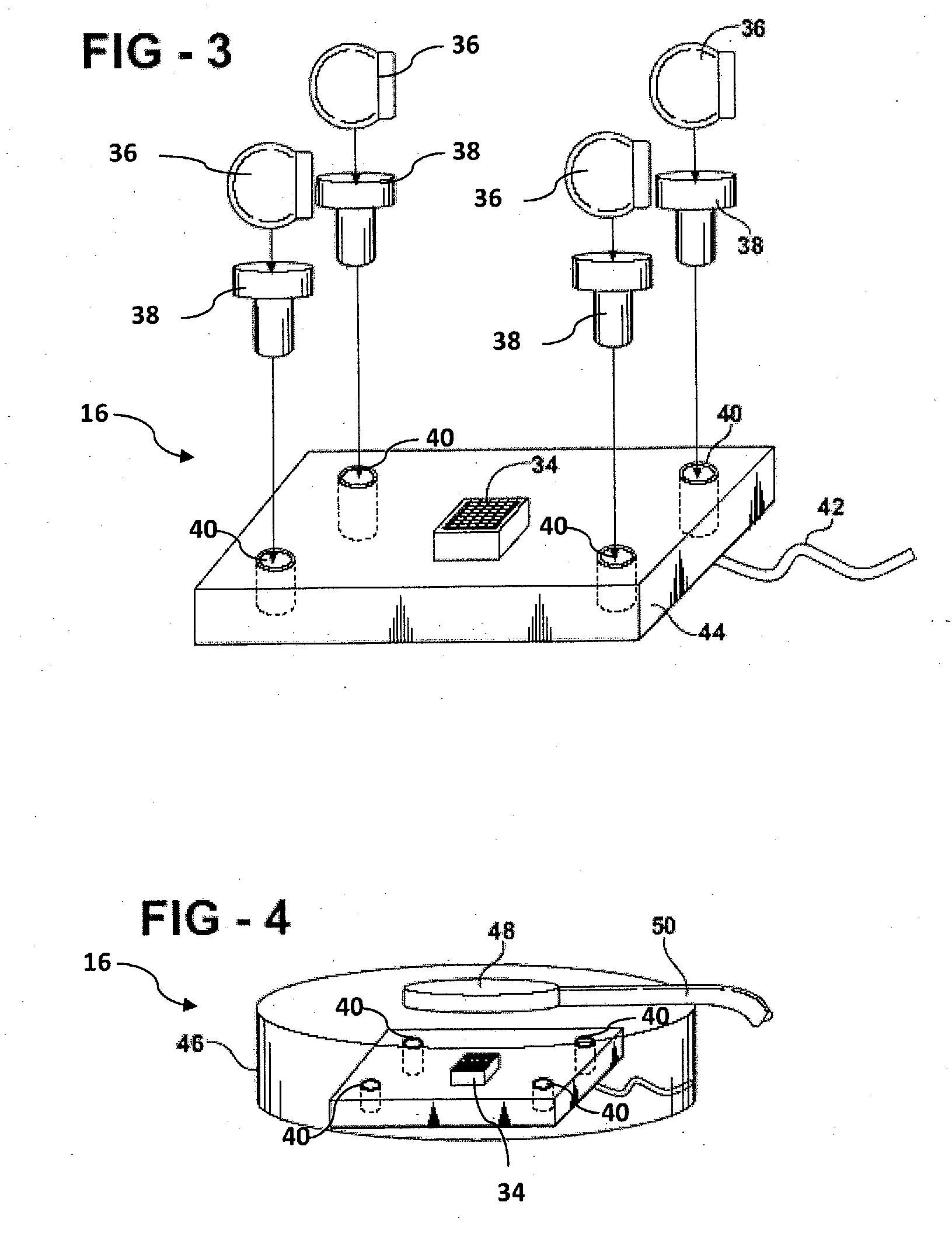
[0036]Referring to the Figures, wherein numerals indicate like or corresponding parts, an inventive system and method for robotic and equipment accuracy enhancement is generally shown at 10 in FIG. 6. The system 10 includes a plurality of multi-axial devices, generally shown at 12 in FIGS. 1 and 2. These multi-axial devices 12, i.e. beacons, are capable of steering a light beam 14, such as a laser, LED, or incoherent source without limiting the scope of the present invention. Typically, the multi-axial device would be a gimbal as shown in FIG. 1, which illustrates a front view of the multi-axial device 12 and FIG. 2, which illustrates a side view of the multi-axial device 12. Those skilled in the art will appreciate that other devices for generating and steering light beams may be used with the present invention without limiting the scope of the present invention. The beacon 12 presents a certain mechanical pointing resolution (the ability to physically point the beam to a commanded...


PUM


Abstract

The inventive concept of the metrology system (the system) actively determines the 6 Degree of Freedom (6-DOF) pose of a motion device such as, but not limited to, an industrial robot employing an end of arm tool (EOAT). A concept of the system includes using laser pointing devices without any inherent ranging capability in conjunction with the EOAT-mounted targets to actively determine the pose of the EOAT at distinct work positions of at least one motion device.

Description

RELATED APPLICATIONS[0001]This is a non-provisional patent application that claims priority to a provisional patent application Ser. No. 61 / 070,614 filed on Mar. 21, 2008 and incorporated herewith by reference in its entirety.FIELD OF THE INVENTION[0002]The present invention relates to systems for robotic and equipment accuracy enhancement and methods.BACKGROUND OF THE INVENTION[0003]In the field of robotics and Numerically Controlled (NC) motion systems, a great amount of effort and research has been dedicated to modeling and characterizing said motion devices and motion systems in pursuit of accuracy enhancement. With industrial robots in particular, manufacturers and after-market companies have focused mainly on modeling the ‘as-built’ conditions of a robot. Usually, parameters in the kinematic model of the robot are adjusted based on the results of a one-time volumetric calibration of the robot in a variety of poses throughout its work envelope; typically, an external metrology ...

Claims


Application Information

Patent Timeline
Patent Type & Authority Applications(United States)
IPC IPC(8): G05B19/04G05B19/418G06F19/00B25J19/02B25J9/00
CPCB25J9/1692G05B2219/40623G05B2219/36439
Inventor BORDYN, BRETT ALANMARKEY, MYLES DANIELKLEEMANN, MICHAEL JOHN
Owner VARIATION REDUCTION SOLUTIONS
Why Eureka
Try Eureka