
Substrate processing apparatus

a processing apparatus and substrate technology, applied in the direction of chemical vapor deposition coating, metal material coating process, coating, etc., can solve the problems of degrading evaporation performance, increasing pressure, reducing yield, etc., to reduce the increase of pressure inside the purge gas supply pipe and the degradation of evaporation performance of an evaporator

Inactive Publication Date: 2009-10-01
KOKUSA ELECTRIC CO LTD
View PDF4 Cites 9 Cited by
  • Summary
  • Abstract
  • Description
  • Claims
  • Application Information

AI Technical Summary

Benefits of technology

The present invention aims to prevent the generation of particles and the degradation of evaporation performance in a substrate processing apparatus. To achieve this, the invention provides a gas supply unit with a joint part that eliminates dead space between different gas supply pipes and reduces the pressure inside the purge gas supply pipe. The joint part includes a diffusion chamber and a flow rate diaphragm, which allows for the simultaneous introduction of evaporated gas and inert gas. The purge gas is sprayed into the diffusion chamber and exhausts through the flow path while sucking residual process gas from the joint part. This results in a more efficient purge and reduced particle generation.

Problems solved by technology

Furthermore, if the wafer is contaminated by particles, quality is deteriorated and yield is decreased.
Moreover, in case where the inert gas is supplied as the carrier gas, if the flow rate of the carrier gas increases, pressure inside the process gas supply pipe 6 increases, which will increase pressure of an evaporation chamber of the evaporator and degrade evaporation performance.

Method used


Image

  • Substrate processing apparatus
  • Substrate processing apparatus
  • Substrate processing apparatus

Examples


Embodiment Construction

[0026]Hereinafter, preferred embodiments will be described with reference to the attached drawings.

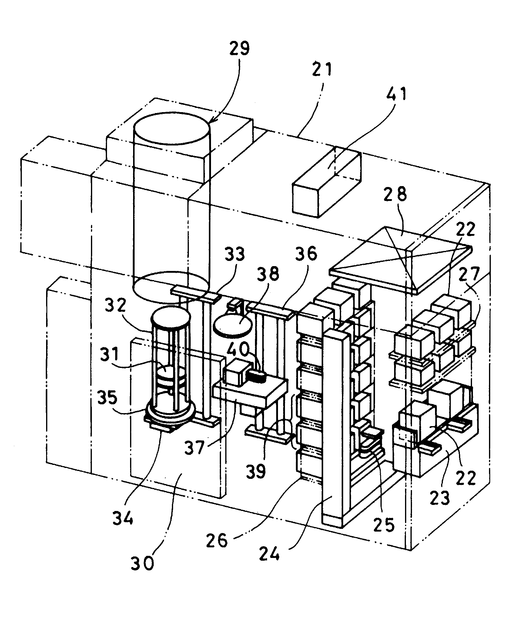
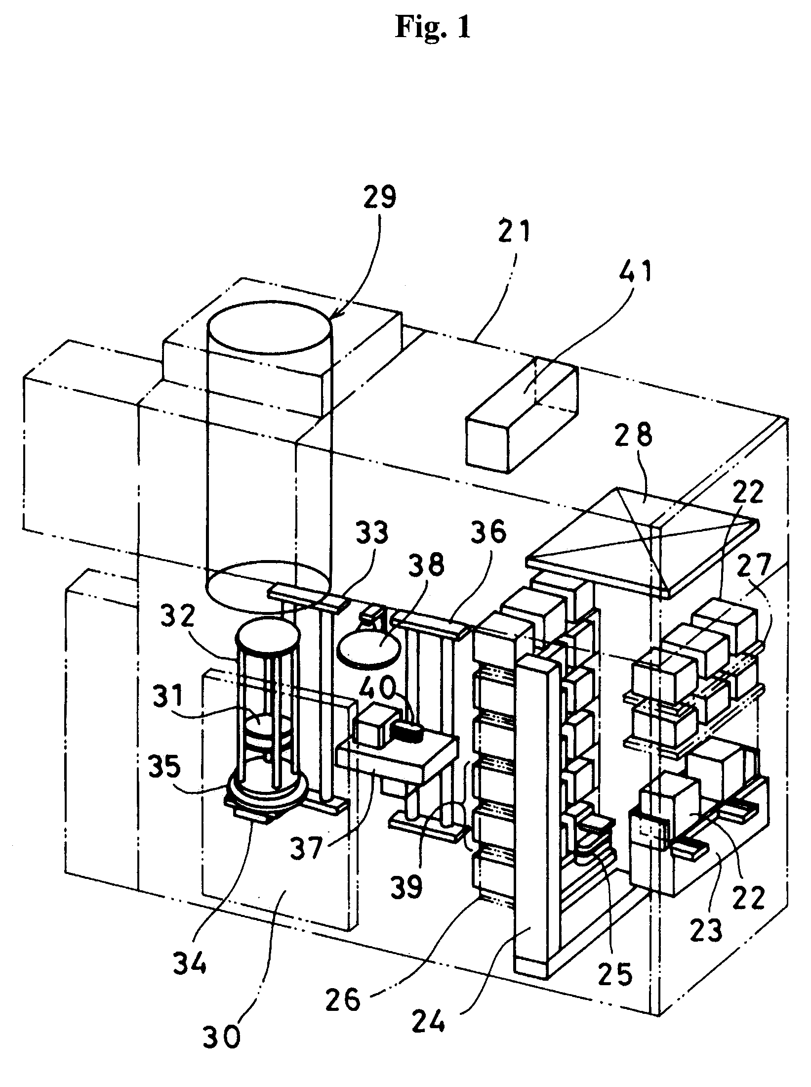
[0027]FIG. 1 illustrates an example of a substrate processing apparatus according to the present invention.

[0028]First, a substrate processing apparatus according to the present invention will be schematically described.

[0029]At the front side of the inside of a housing 21, a cassette stage 23 is installed as a container delivery means for giving and receiving cassettes 22 as a substrate container to / from an external transfer device (not shown). At the rear side of the cassette stage 23, a cassette elevator 24 is installed as an elevating means. At the cassette elevator 24, a cassette transfer device 25 is installed as a cassette transfer means. Furthermore, at the rear side of the cassette elevator 24, a cassette shelf 26 is installed as a cassette accommodating means. At the upward part of the cassette stage 23, a standby cassette shelf 27 is installed as a cassette accommodating mea...


PUM

PropertyMeasurementUnit
exposure timeaaaaaaaaaa
pressureaaaaaaaaaa
temperatureaaaaaaaaaa

Abstract

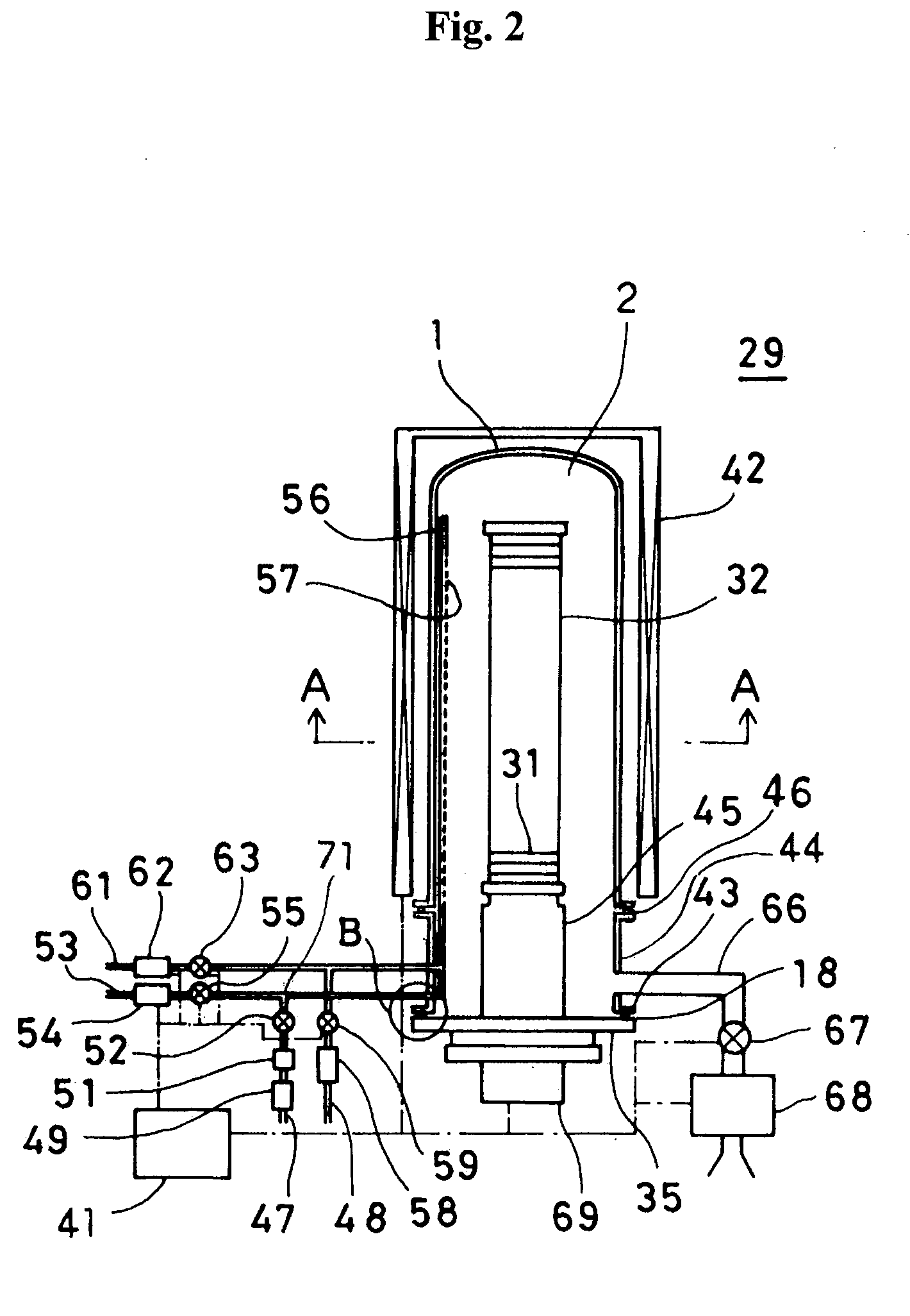
A substrate processing apparatus comprises: a processing chamber configured to accommodate a substrate; and a gas supply unit configured to supply gas into the process chamber. The gas supply unit comprises: an evaporator configured to evaporate a liquid material; a first gas supply pipe configured to supply an evaporated gas from the evaporator into the process chamber; a second gas supply pipe configured to supply an inert gas into the process chamber; and a joint part at which the first gas supply pipe and the second gas supply pipe are joined. The joint part includes a diffusion chamber. A flow rate diaphragm having an inner diameter narrowing toward a direction of the diffusion chamber is installed at the front end of the downstream side of the second gas supply pipe. The evaporated gas from the evaporator is introduced into the diffusion chamber and simultaneously the inert gas is introduced through the flow rate diaphragm installed at the front end of the second gas supply pipe.

Description

CROSS-REFERENCE TO RELATED PATENT APPLICATION[0001]This U.S. non-provisional patent application claims priority under 35 U.S.C. §119 of Japanese Patent Application Nos. 2008-095410, filed on Apr. 1, 2008, and 2008-284589, filed on Nov. 5, 2008, in the Japanese Patent Office, the entire contents of which are hereby incorporated by reference.BACKGROUND OF THE INVENTION[0002]1. Field of the Invention[0003]The present invention relates to a substrate processing apparatus which manufactures a semiconductor device by performing a variety of processes such as formation of thin films, diffusion of impurities, etching, or annealing on a substrate such as a silicon wafer.[0004]2. Description of the Prior Art[0005]A substrate processing apparatus for manufacturing a semiconductor device includes a process furnace which accommodates a substrate such as a silicon wafer in a process chamber and processes the substrate by heating the substrate and introducing a process gas into the process chamber...

Claims


Application Information

Patent Timeline
Patent Type & Authority Applications(United States)
IPC IPC(8): C23C16/44
CPCC23C16/405C23C16/45561C23C16/45544C23C16/4485
Inventor KATO, TSUTOMU
Owner KOKUSA ELECTRIC CO LTD
Learn More