
Exposed coil rocker arm cover assembly having external multi-coil mounting bracket

a rocker arm cover and exposed coil technology, applied in the direction of machines/engines, lubrication of auxillaries, combustion air/fuel air treatment, etc., can solve the problems of unit weight and torsional strain on the plugs, and achieve the effect of reducing the degradation of the gasket material, preventing leakage, and prolonging the life of the gask

Inactive Publication Date: 2009-10-01
HARBERT RICHARD H
View PDF13 Cites 29 Cited by
  • Summary
  • Abstract
  • Description
  • Claims
  • Application Information

AI Technical Summary

Benefits of technology

"The invention is a rocker arm cover for internal combustion engines that improves performance and reduces emissions. The cover has a unique design that allows for independent servicing or replacement of the rocker arm chamber housing and coils. The cover also includes a bracket for securely attaching the cover to the engine head. The bracket is designed to accommodate a variety of housing lengths and placement of the securing bosses. The cover also includes a conduit for oil fill and a PCV valve for pressure balance. The cover is made of aluminum or a rugged plastic or composite composition, and is secured to the engine head using mounting bolts. The cover design reduces the likelihood of leaks and allows for separate servicing or replacement of the coils."

Problems solved by technology

This approach suffers the serious disadvantage of having no separate oil fill, requires removal of 13 bolts to remove the base cover to access the plugs, and it houses the plugs and boots in the “wet” zone, the same space as the rocker arms, where they are continuously exposed to oil and hydrocarbon vapors.
This unit is independent of a rocker arm cover and rides on the plugs themselves, rather than being separately mounted, so the unit puts weight and torsional strain on the plugs.

Method used


Image

  • Exposed coil rocker arm cover assembly having external multi-coil mounting bracket
  • Exposed coil rocker arm cover assembly having external multi-coil mounting bracket
  • Exposed coil rocker arm cover assembly having external multi-coil mounting bracket

Examples


Embodiment Construction

[0026]The following detailed description illustrates the invention by way of example, not by way of limitation of the scope, equivalents or principles of the invention. This description will clearly enable one skilled in the art to make and use the invention, and describes several embodiments, adaptations, variations, alternatives and uses of the invention, including what is presently believed to be the best modes of carrying out the invention.

[0027]In this regard, the invention is illustrated in the several figures, and is of sufficient complexity that the many parts, interrelationships, and sub-combinations thereof simply cannot be fully illustrated in a single patent-type drawing. For clarity and conciseness, several of the drawings show in schematic, or omit, parts that are not essential in that drawing to a description of a particular feature, aspect or principle of the invention being disclosed. Thus, the best mode embodiment of one feature may be shown in one drawing, and the...


PUM


Abstract

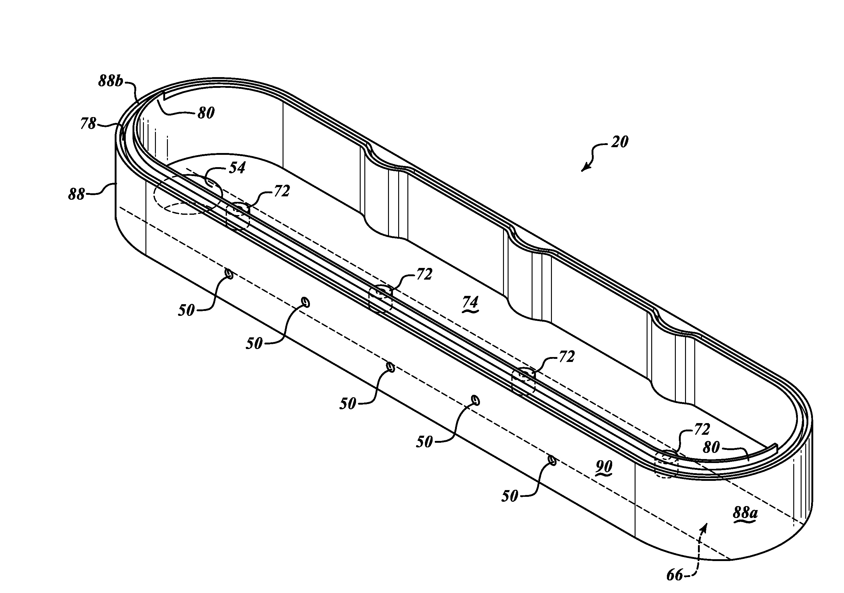
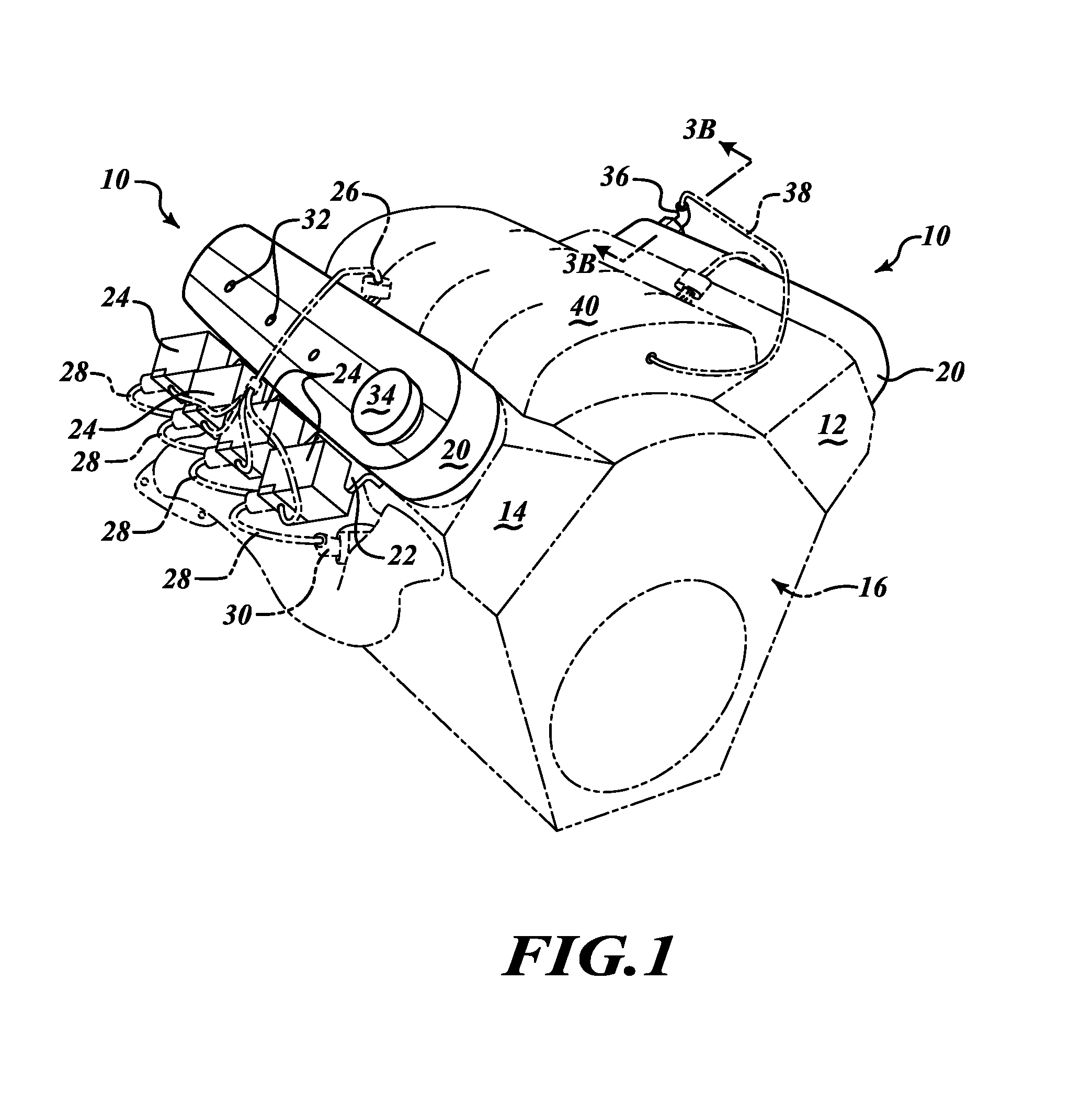
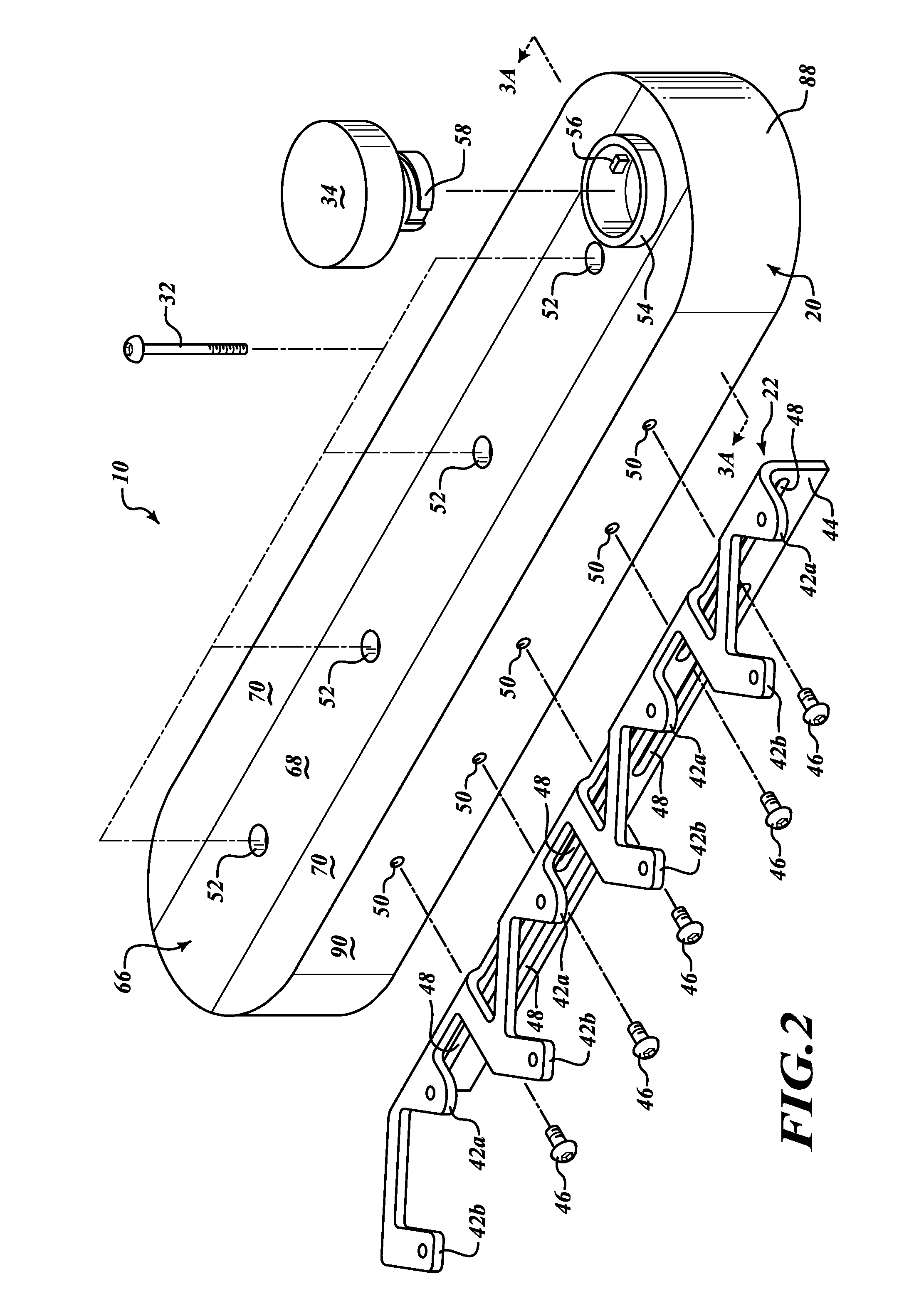
An improved rocker arm cover assembly having an enclosed rocker arm chamber housing and a generally L-shaped bracket for mounting multiple coils to an exterior vertical side wall of the housing, so that the coils are exposed and laterally displaced from the housing. The bottom of the housing includes special seal and flange members to permit sealing mounting to the engine head so that the rocker arm chamber is isolated as a “wet” enclosure from the coil bracket assembly. The housing is mounted directly to the head via a plurality of through bolts. A fully isolated, dual function, oil fill / PCV valve conduit is provided through the top of the housing to permit adding lubrication oil or permitting exhaust of crankcase vapors without contaminating the coils, and permitting independent servicing of the coils. Several variations of coils and coil mounting brackets are disclosed.

Description

FIELD[0001]The invention relates to the field of automotive parts, and more particularly to an improved rocker arm cover assembly having an enclosed rocker arm chamber that includes special seal and flange members to mate with the engine head, and an exposed, exterior bracket plate on which a plurality of coils is mounted. A fully isolated dual-function conduit is provided through the rocker arm chamber top wall to function either as an oil fill tube to permit adding lubrication oil without contaminating the coils or as a crankcase vapor exhaust to the air intake manifold via a PCV valve fitted in the conduit. A plurality of coil and coil mounting bracket designs are disclosed.BACKGROUND[0002]Conventional after-market valve covers or rocker arm covers (RACs) comprise a thin sheet metal or plastic cover mounted on the engine head(s). These covers have a single cavity that encloses the rocker arms, valve return springs and pushrods that together actuate the cylinder valve stems. In mo...

Claims


Application Information

Patent Timeline
Patent Type & Authority Applications(United States)
IPC IPC(8): F01M9/10F02F7/00
CPCF01M11/04F02F7/006F01M13/0011
Inventor HARBERT, RICHARD H.
Owner HARBERT RICHARD H
Learn More