Damping force adjustable shock absorber

a shock absorber and damping force technology, applied in the direction of shock absorbers, vibration dampers, springs/dampers, etc., can solve the problems of abnormal noise generation and overshoot in so as to prevent the occurrence of self-excited vibration, improve the responsiveness of the valve body, and prevent the delay of the damping force control

Active Publication Date: 2009-10-01
HITACHI ASTEMO LTD
View PDF5 Cites 60 Cited by
  • Summary
  • Abstract
  • Description
  • Claims
  • Application Information

AI Technical Summary

Benefits of technology

[0006]The present invention has been contrived in consideration of the above-mentioned circumstances, and an object thereof is to provide a damping force adjustable shock absorber in which it is possible to prevent response delay of a pressure control valve and occurrence of self-excited vibration of a valve body.
[0008]According to the damping force adjustable shock absorber of the present invention, it is possible to improve the responsiveness of the valve body and therefore to prevent response delay in a damping force control. In addition, since the natural frequency of the valve body can be set to a high value, it is possible to prevent occurrence of self-excited vibration.

Problems solved by technology

For example, if the damping force adjustable shock absorber is mounted on a suspension control apparatus of a vehicle such as an automobile, and performs a damping force control by receiving a control signal from a controller according to a running condition of the vehicle, response delay may occur due to, for example, the inertia of the plunger of the pressure control valve (solenoid valve), leading to overshoot in the damping force control.
In addition, abnormal noises may be generated due to self-excited vibration of the valve body of the pressure control valve.

Method used


Image

  • Damping force adjustable shock absorber
  • Damping force adjustable shock absorber
  • Damping force adjustable shock absorber

Examples


Embodiment Construction

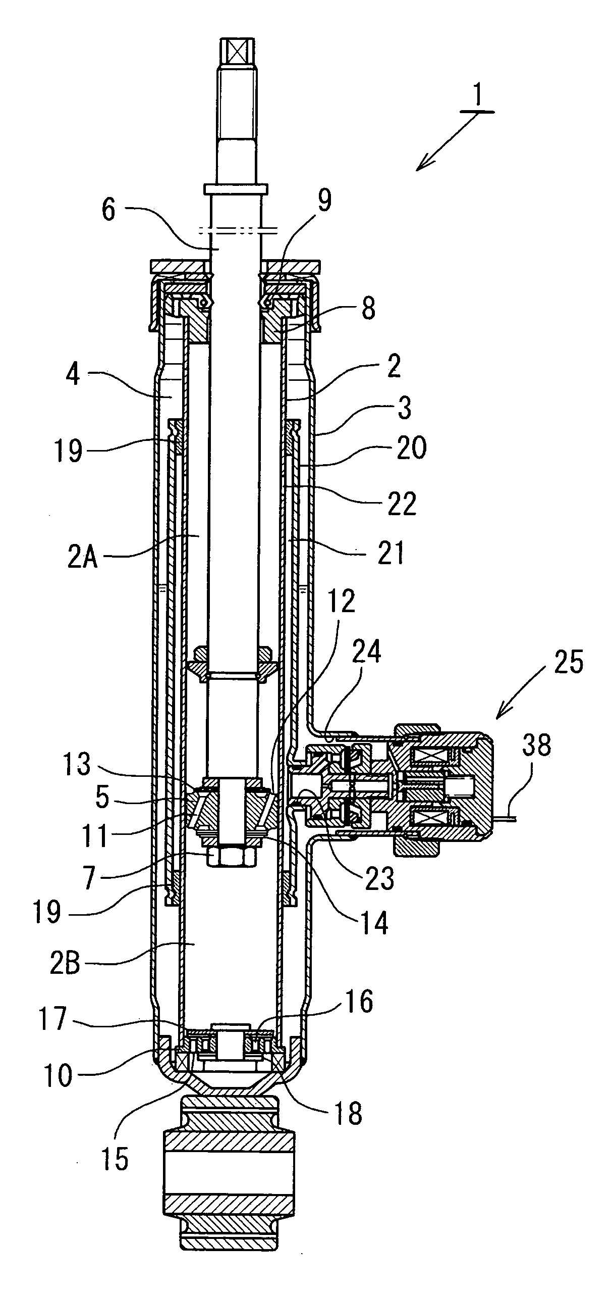
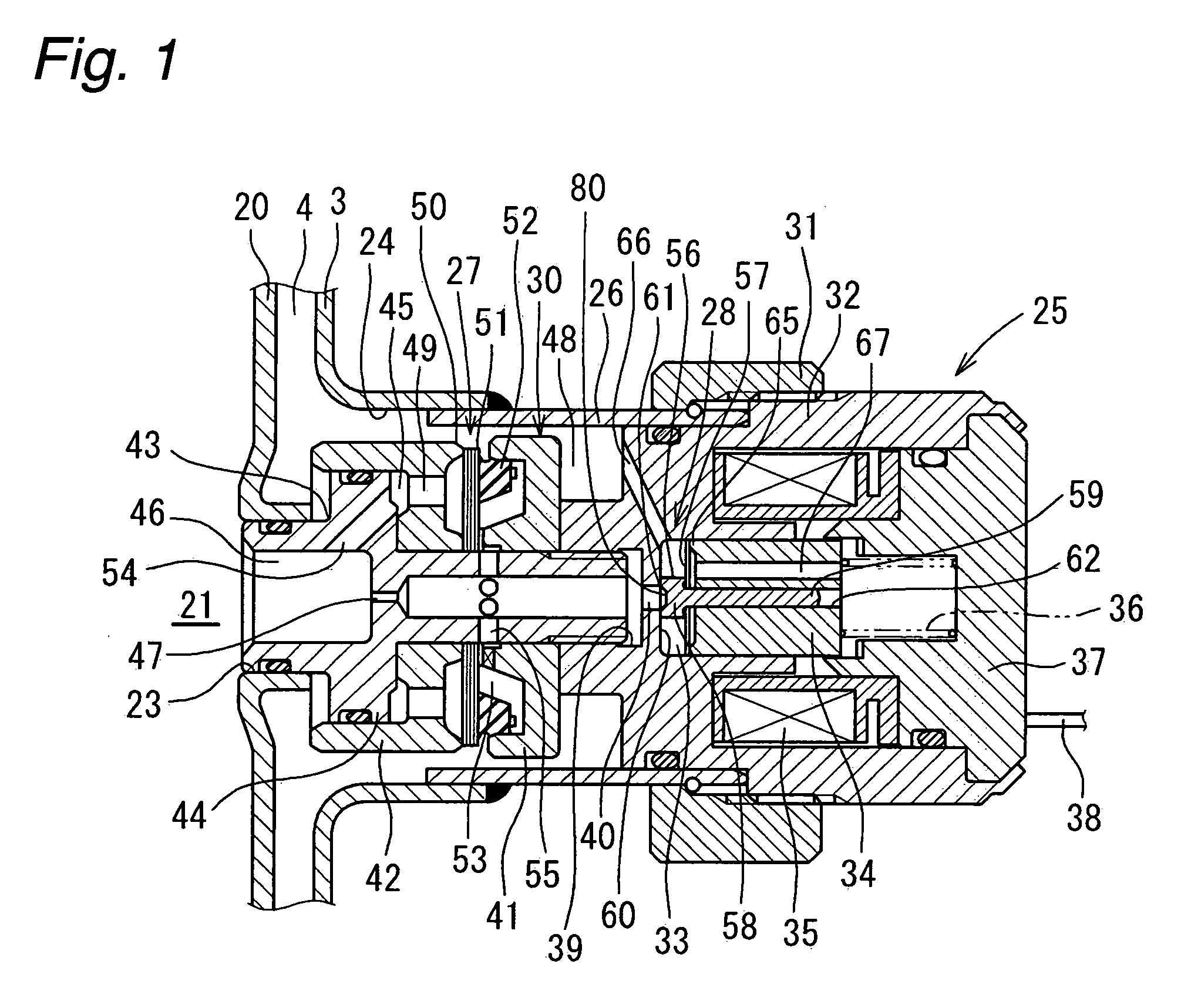
[0023]A first embodiment of the present invention will now be described with reference to the accompanying drawings. As shown in FIG. 4, a damping force adjustable hydraulic shock absorber 1 (damping force adjustable shock absorber) according to the first embodiment has a double-cylinder structure including a cylinder 2 disposed in an outer cylinder 3, and a reservoir 4 is formed between the cylinder 2 and the outer cylinder 3. A piston 5 is slidably fitted in the cylinder 2, and the inside of the cylinder 2 is separated into two chambers, a cylinder upper chamber 2A and a cylinder lower chamber 2B by the piston 5. One end of a piston rod 6 is coupled to the piston 5 by a nut 7, and the other end of the piston rod 6 extends to the outside of the cylinder 2 through the cylinder upper chamber 2A, and a rod guide 8 and an oil seal 9 attached to the upper ends of the cylinder 2 and the outer cylinder 3. A base valve 10 for separating the cylinder lower chamber 2B and the reservoir 4 is ...


PUM


Abstract

An object of the present invention is to provide a damping force adjustable hydraulic shock absorber, in which response delay of a pressure control valve and self-excited vibration of a valve body can be prevented. A damping force is generated by controlling an oil flow between an annular oil passage 21 and a reservoir 4 generated by a sliding movement of a piston in a cylinder with use of a back-pressure type main valve 27 and a pressure control valve 28. The damping force is directly generated by the pressure control valve 28, and a valve-opening pressure of the main valve 27 is adjusted by adjusting an inner pressure of a back-pressure chamber 53. In the pressure control valve 28, a valve spring 57 is disposed between a valve body 56 and a plunger 34. A mass of the valve body 56 is sufficiently less than that of a plunger 34, and a spring stiffness of the valve spring 57 is higher than that of a plunger spring 36. As a result, it is possible to improve the responsiveness of the valve body 56 to prevent response delay in a damping force control. In addition, since the natural frequency of the valve body 56 is high, it is possible to prevent self-excited vibration of the valve body 56.

Description

BACKGROUND OF THE INVENTION[0001]The present invention relates to a damping force adjustable shock absorber mounted on, for example, a suspension apparatus of a vehicle such as an automobile.[0002]Generally, in a damping force adjustable shock absorber mounted on a suspension apparatus of an automobile, a piston coupled to a piston rod is slidably fitted in a cylinder sealingly containing oil, whereby the inside of the cylinder is divided into two chambers, and a damping force is generated by controlling an oil flow generated by a sliding movement of the piston in the cylinder with use of a damping force generating mechanism comprising an orifice, a disk valve and others. In addition, the damping force is adjusted by changing flow resistance of the damping force generating mechanism with use of, for example, a flow control valve or a pressure control valve.[0003]As this kind of damping force adjustable shock absorber, for example, Japanese Patent Public Disclosure No. 2001-12534 dis...

Claims


Application Information

Patent Timeline
Patent Type & Authority Applications(United States)
IPC IPC(8): F16F9/46
CPCF16F9/464
Inventor NAKADATE, TAKAONEZU, TAKASHIKATAYAMA, YOHEIKATAYAMA, SHIGEOYABE, HIROYUKI
Owner HITACHI ASTEMO LTD
Why Eureka
Try Eureka