Piezoelectric element drive device, electronic apparatus, and method for controlling piezoelectric element drive frequency

a technology of piezoelectric elements and drive devices, which is applied in the direction of machines/engines, generators/motors, and positive displacement liquid engines, etc., can solve the problems of increasing costs, and achieve the effect of reliable driving, sufficient accuracy and sufficient accuracy

Inactive Publication Date: 2009-10-01
SONY CORP
View PDF4 Cites 46 Cited by
  • Summary
  • Abstract
  • Description
  • Claims
  • Application Information

AI Technical Summary

Benefits of technology

[0013]It is thus desirable to provide a piezoelectric-element drive device that is capable of reliably driving, even with a small circuit scale, a piezoelectric element at a resonant frequency and with practically sufficient accuracy. It is also desirable to provide an electronic apparatus that utilizes the piezoelectric-element driving to drive a fluid pump. It is further desirable to provide a method for controlling the frequency of piezoelectric-element driving that can be performed with practically sufficient accuracy, even with a simple operation procedure.
[0033]With the drive device, when the control signal is input to the primary side of the transformer, the drive signal whose frequency varies in accordance with the control signal is generated at the secondary side of the transformer. The piezoelectric element is connected to the secondary side of the transformer and a resonant circuit including the piezoelectric element is provided. When the resonant frequency of the resonant circuit and the drive-signal frequency substantially match each other, the resonant frequency operates at high efficiency.
[0050]According to the present invention, it is possible to provide a piezoelectric-element drive device that is capable of reliably driving, even with a small circuit scale, a piezoelectric element at a resonant frequency with practically sufficient accuracy. It is also possible to provide an electronic apparatus that utilizes the piezoelectric-element driving to drive a fluid pump. It is further possible to provide a method for controlling the frequency of piezoelectric-element driving that can be performed with practically sufficient accuracy, even with a simple operation procedure.

Problems solved by technology

However, the drive frequency control using phase comparison typically involves a large circuit scale for the phase comparison, which leads to an increase in cost.

Method used


Image

  • Piezoelectric element drive device, electronic apparatus, and method for controlling piezoelectric element drive frequency
  • Piezoelectric element drive device, electronic apparatus, and method for controlling piezoelectric element drive frequency
  • Piezoelectric element drive device, electronic apparatus, and method for controlling piezoelectric element drive frequency

Examples


first embodiment

[0067]A first embodiment of the present invention is directed to a drive device for a piezoelectric element.

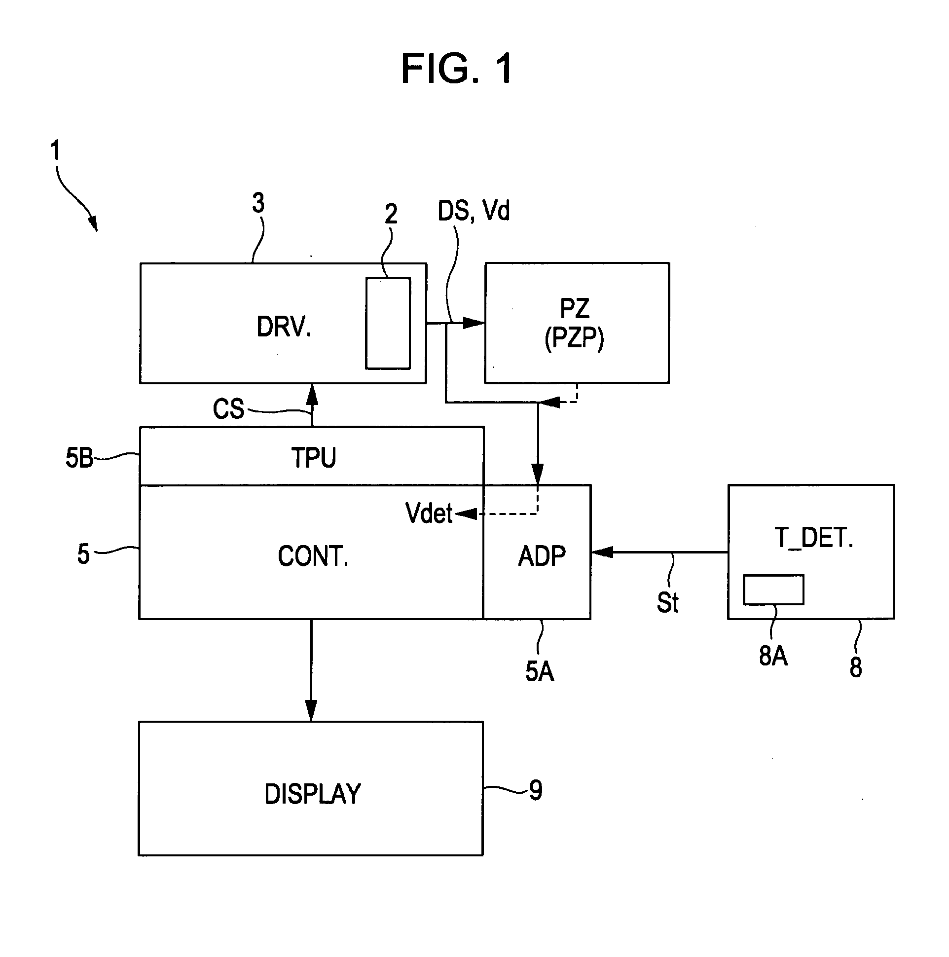
[0068]FIG. 1 is a bock diagram of a drive device for a piezoelectric element PZ.

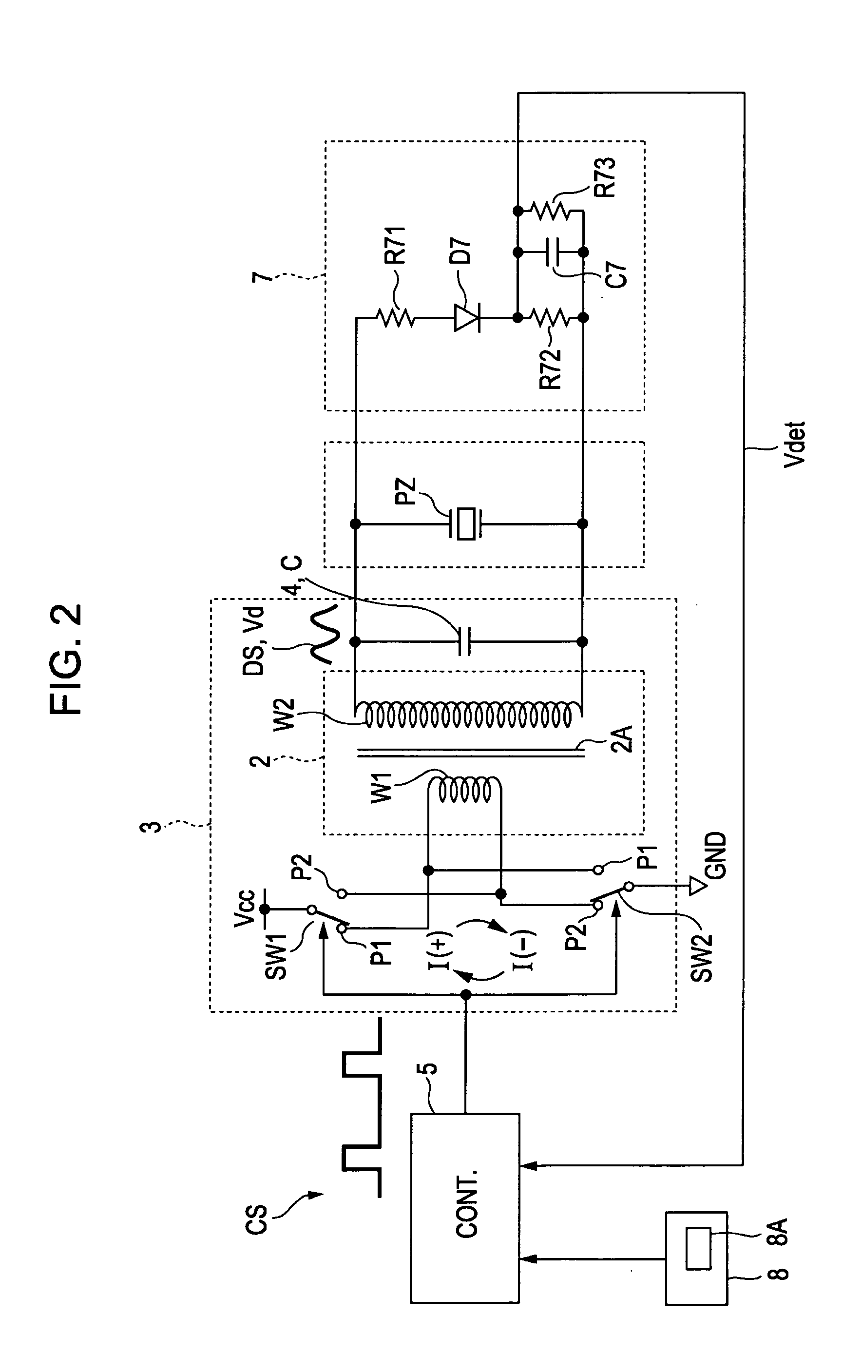
[0069]A drive device 1 illustrated in FIG. 1 includes an electromagnetic coupling transformer 2, a drive circuit (DRV.) 3, a controller (CONT.) 5, a temperature detection circuit (T_DET.) 8, and a display 9. The controller 5 includes a microcomputer or the like to serve as a control circuit.

[0070]In the drive device 1, the electromagnetic coupling transformer 2, the drive circuit 3, and the controller 5 are main components for driving the piezoelectric element PZ, and the temperature detection circuit 8 and the display 9 are optional.

[0071]In FIG. 1, the controller 5 has an analog-to-digital conversion port (shown as “ADP” and hereinafter referred to as an “AD port”) 5A and a timer pulse unit (TPU) 5B for controlling, for example, generation and stopping of a control signal CS having a predetermine...

second embodiment

[0180]Although the processing loop in FIG. 6 is cyclically executed in the first embodiment described above, the cycle of the processing loop in a second embodiment is varied according to a temperature. Thus, the drive device 1 in the second embodiment has, as a basic element, the temperature detection circuit 8 shown in FIG. 1, particularly, a temperature detection element 8A included therein.

[0181]The temperature detection circuit 8 is provided to keep track of a temperature at a location where the piezoelectric element PZ and the drive device 1 are disposed, for example, a temperature inside electronic equipment in which they are incorporated. The temperature detection element 8A included in the temperature detection circuit 8 is a device having a parameter that varies according to a temperature. Examples of the temperature detection element 8A include a temperature sensor and a thermistor. The temperature detection circuit 8 includes, in addition to the temperature detection ele...

third embodiment

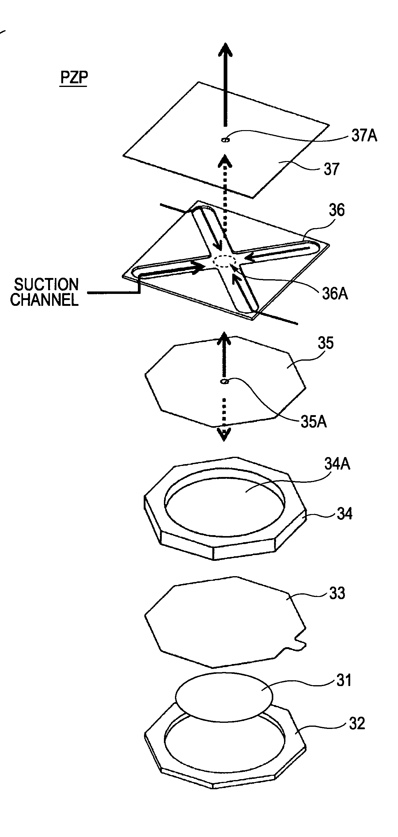
[0185]A third embodiment is directed to a pump device, which is an example of application of the drive circuit according to the first or second embodiment described above. The pump device according to the third embodiment of the present invention can be applied to a variety of pump devices for air, other gases, and fluids such as liquids. A description below is particularly given of an air pump device that is applicable to an air-cooling device that air-cools a heated object (e.g., an electronic device, such as an IC), a device that produces constant airflow in a narrow conduit, or the like.

[0186]An air pump device is useful as a countermeasure system against an internal-temperature increase in mobile equipment or stationary equipment. In particular, since the housing of mobile equipment is small, there are cases in which a legacy fan-type air-cooling device cannot be disposed therein.

[0187]A piezoelectric-element-based air-pump device (hereinafter, simply referred to as a “piezoele...


PUM


Abstract

A drive device for a piezoelectric element includes a transformer, a driver circuit, and a control circuit. The transformer has a primary side and a secondary side. The drive circuit causes the secondary side to generate a drive signal whose frequency varies in accordance with a control signal input to the primary side and to supply the generated drive signal to the piezoelectric element. The control circuit changes a frequency of the control signal in a predetermined frequency range multiple times, detects an impedance change in the piezoelectric element each time the control-signal frequency is changed, determines a resonant frequency of the piezoelectric element on the basis of a transition of the impedance change, and controls the control-signal frequency so that the determined resonant frequency is obtained.

Description

CROSS REFERENCES TO RELATED APPLICATIONS[0001]The present invention contains subject matter related to Japanese Patent Application JP 2008-080273 filed in the Japanese Patent Office on Mar. 26, 2008, the entire contents of which are incorporated herein by reference.BACKGROUND OF THE INVENTION[0002]1. Field of the Invention[0003]The present invention relates to a piezoelectric-element drive device that can change a drive frequency, an electronic apparatus having a fluid pump using a piezoelectric element, and a method for controlling the driving frequency of a piezoelectric element.[0004]2. Description of the Related Art[0005]Piezoelectric-element drive circuits that are preferably used for liquid sprayers and various types of actuator have been proposed (e.g., refer to Japanese Patent Nos. 2618685 and 3115618.[0006]In such a drive circuit, a transistor for switching is connected to a primary winding of a transformer and a piezoelectric element is connected to a secondary winding the...

Claims


Application Information

Patent Timeline
Patent Type & Authority Applications(United States)
IPC IPC(8): H02N2/06F04B49/06
CPCF04B43/046H02N2/008H01L41/042H10N30/802
Inventor OHSAWA, TAKAO
Owner SONY CORP
Why Eureka
Try Eureka