Surveying system

Active Publication Date: 2009-10-01
KK TOPCON
View PDF14 Cites 39 Cited by
  • Summary
  • Abstract
  • Description
  • Claims
  • Application Information

AI Technical Summary

Benefits of technology

[0010]The present invention provides a surveying system, which comprises a surveying device having a function for tracking a target and a remote control device for remotely controlling the surveying device on a target side, wherein the surveying device comprises measuring units, image pickup units, a first radio unit, and a first control arithmetic unit, and the remote control device comprises a second radio unit, a second control arithmetic unit, a second display unit, and a second operation input unit, wherein the surveying device transmits an image data acquired at the image pickup unit to the remote control device via the radio unit, and the remote control device receives the image data via the second radio unit and the second display unit displays the image in inversion display based on the image data. As a result, an operating direction in the image concurs with an operating direction of the surveying device as recognized by the operator when the surveying device is operated by the remote control device. This makes it possible to perform the operation in simple and easy manner, and to improve a working efficiency.
[0011]Also, the present invention provides the surveying system as described above, wherein the second display unit can select normal vision display or inversion display. As a result, it is possible to select an image, which matches the direction of the operator's line of sight

Problems solved by technology

However, even when the distance and the direction to the measuring point are displayed on the display unit, it is difficult to sensually identify in which direction and how

Method used


Image

  • Surveying system
  • Surveying system
  • Surveying system

Examples


Embodiment Construction

[0021]A description will be given below on a best mode for carrying out the present invention by referring to the attached drawings.

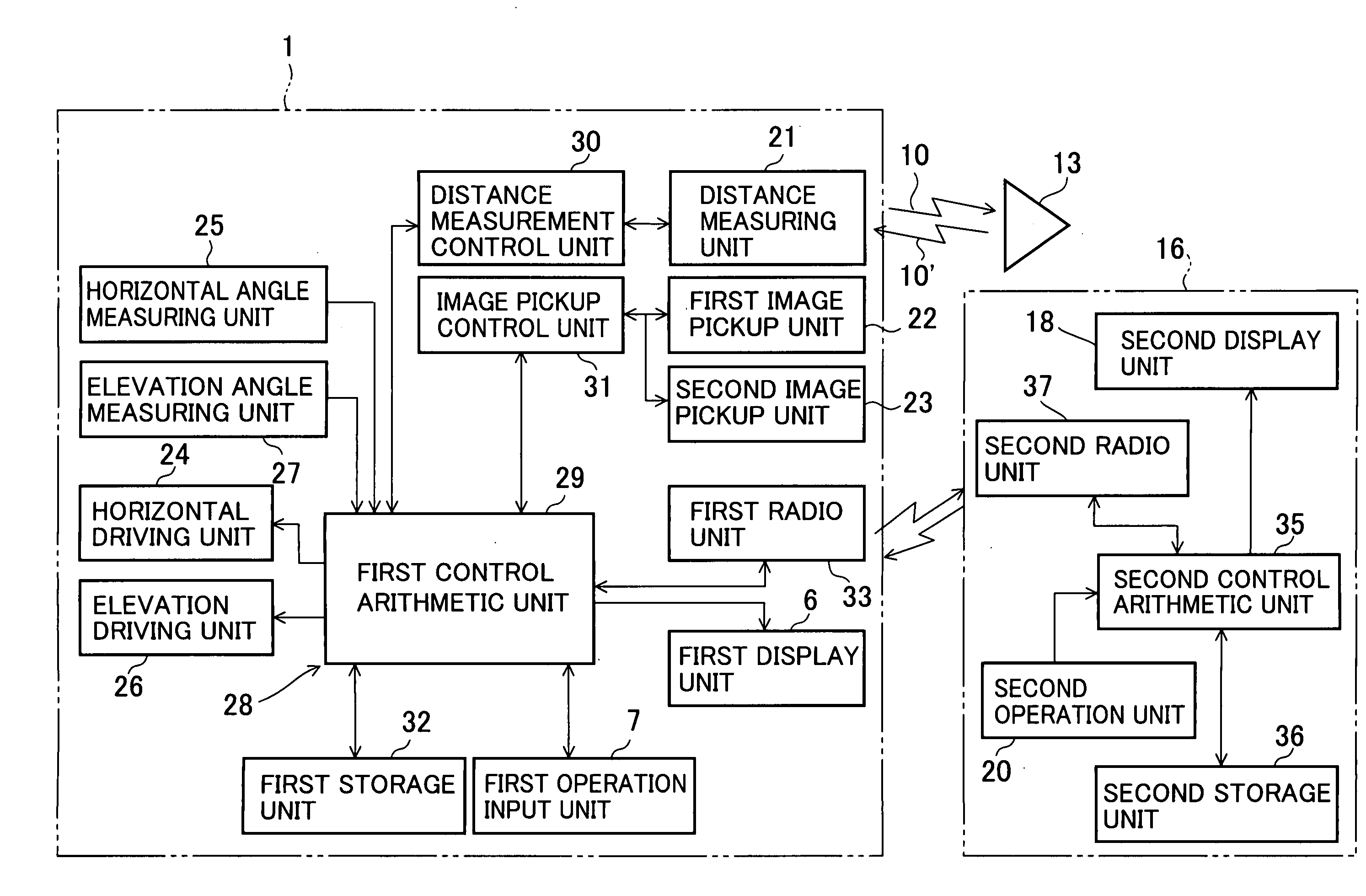
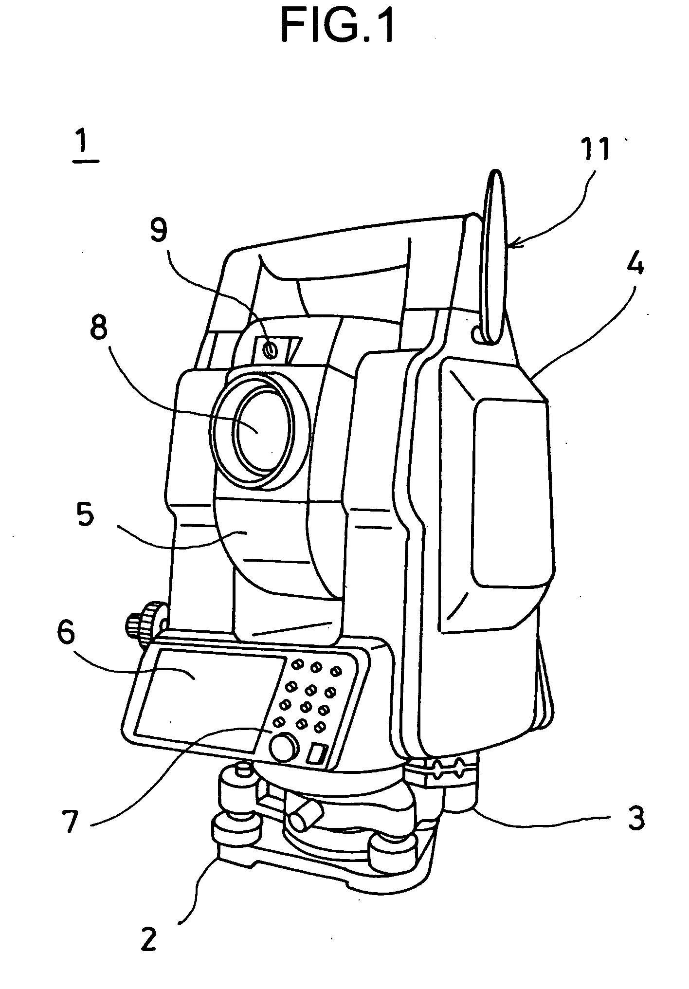
[0022]FIG. 1 shows an example of a surveying device 1, which constitutes a surveying system of the present invention. The surveying device used in this case is a total station, for instance. A pulsed laser beam is projected to a measuring point. A pulsed reflection light from the measuring point is received, and a distance measurement is performed for each pulse. The results of the distance measurements are averaged, and the distance is measured with high accuracy.

[0023]The surveying device 1 primarily comprises a leveling unit 2 installed on a tripod (not shown), a base unit 3 mounted on the leveling unit 2, a frame unit 4 rotatably mounted around an elevation axis center on the base unit 3, and a telescope unit 5 rotatably mounted around a horizontal axis center on the frame unit 4.

[0024]The frame unit 4 comprises a first display unit 6 and a first op...


PUM


Abstract

The present invention provides a surveying system, which comprises a surveying device 1 having a function for tracking a target 13 and a remote control device 16 for remotely controlling the surveying device on a target side, wherein the surveying device comprises measuring units 21, 25 and 27, image pickup units 22 and 23, a first radio unit 33, and a first control arithmetic unit 29, and the remote control device comprises a second radio unit 37, a second control arithmetic unit 35, a second display unit 18, and a second operation input unit 20, wherein the surveying device transmits an image data acquired at the image pickup unit to the remote control device via the radio unit, and the remote control device receives the image data via the second radio unit and the second display unit displays the image in inversion display based on the image data.

Description

BACKGROUND OF THE INVENTION[0001]The present invention relates to a surveying system. In particular, the invention relates to a surveying system for tracking a target.[0002]As a surveying device for measuring a distance, a horizontal angle, and an elevation angle, a type of surveying device with a tracking function has been known in the past. In this type of surveying device, an object reflector (a target) such as a corner cube is collimated by a collimating telescope, which is provided on the surveying device. A tracking light is projected from the collimating telescope, and when the target is moved, a reflection light from the target is received, and the target is automatically tracked.[0003]In this type of the surveying device with tracking function, an operator needs not be on a surveying device side. The surveying operator performs an operation on a target side, and a measurement can be carried out by a single operator. For instance, the surveying operator holds a remote contro...

Claims


Application Information

Patent Timeline
IPC IPC(8): H04N7/18G09G5/00G06F3/041
CPCG01C15/002G01C1/04
Inventor NAGASHIMA, TERUKAZUSHINOZAKI, HAJIMEMIYAO, YOSHIKATSU
Owner KK TOPCON
Why Eureka
Try Eureka