Image generation method and device for emission computed tomography

a computed tomography and image generation technology, applied in tomography, applications, instruments, etc., can solve the problems of long time pet examination pain for patients, and it is extremely difficult to transform e image information for each motion phase, so as to achieve clear functional image information in a short time

Inactive Publication Date: 2009-10-01
HITACHI LTD
View PDF9 Cites 18 Cited by
  • Summary
  • Abstract
  • Description
  • Claims
  • Application Information

AI Technical Summary

Benefits of technology

[0020]According to the present invention, it is possible to obtain clear functional image information of a living organ in a short time, targeting at a region that moves under the influence of respiration and cardiac beat.

Problems solved by technology

However, a long time PET examination is a pain to a patient (in most cases, a patient having a disease).
For this reason, usually, it is extremely difficult to transform E image information for each motion phase and superimpose these pieces of information onto each other.

Method used


Image

  • Image generation method and device for emission computed tomography
  • Image generation method and device for emission computed tomography
  • Image generation method and device for emission computed tomography

Examples


embodiment 1

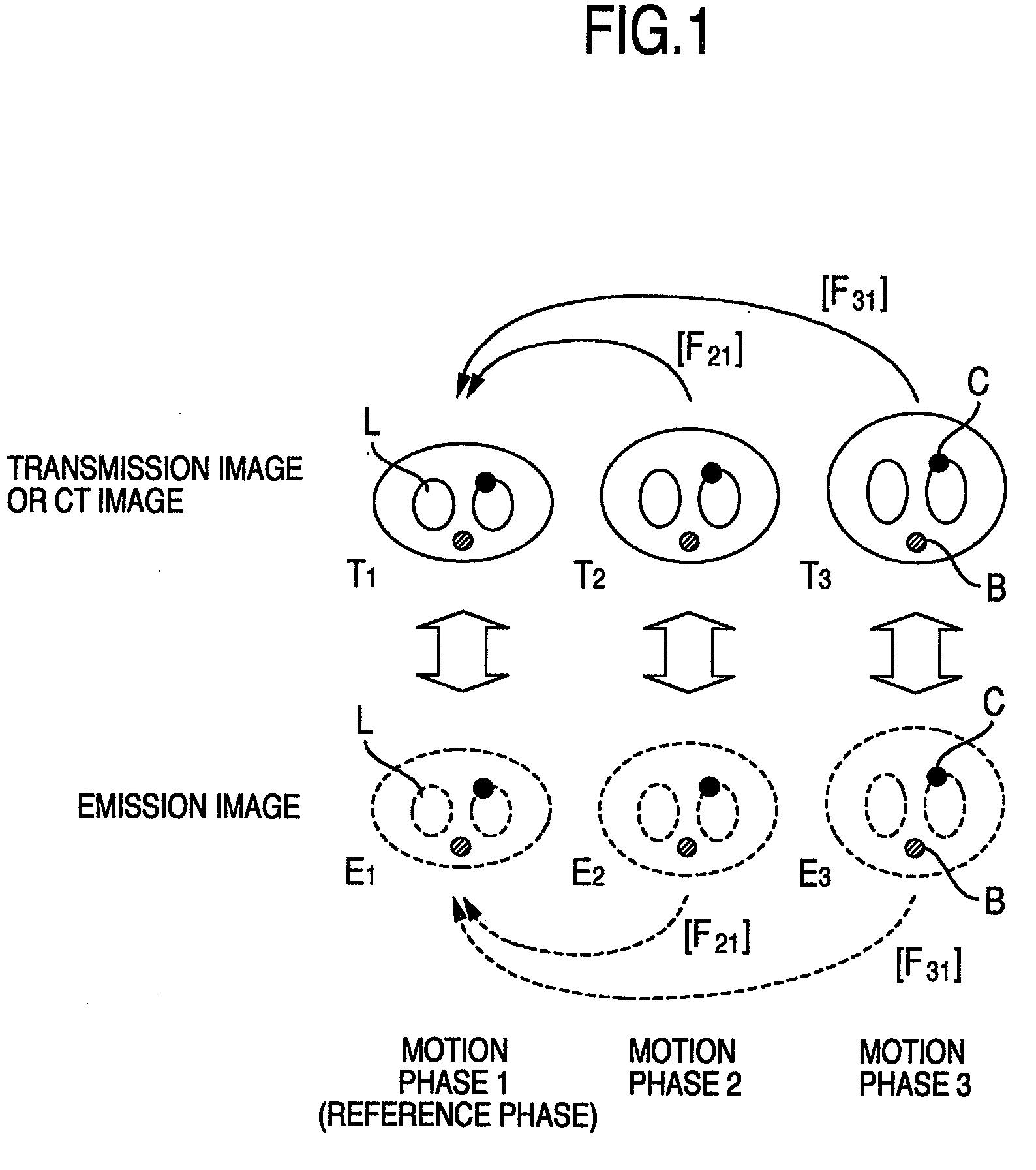
[0032]Blurring of image information due to a patient motion has been a problem in the following points.

[0033](1) The body contour and the contour of an internal organ and a tumor will blur.

[0034](2) In a region having a high degree of accumulation of radiopharmaceuticals, the degree of accumulation is underestimated than the actual one and the diagnostic performance will degrade.

[0035](3) superimpose of image information with a plurality of modalities does not work well.

[0036]The above problems are fundamental influences which a patient motion has on the image information. At present when the spatial resolution of a PET device has dramatically increased, (1) and (2) are of interest as the major factors damaging the image quality. With regard to (3), even at present when superimpose of image information has become popular due to the recently-emerged combined PET / CT device (see Journal of Nuclear Medicine, Vol. 45, No. 8, PP. 1287-292), mainly in the fields of radiation therapy, biops...

embodiment 2

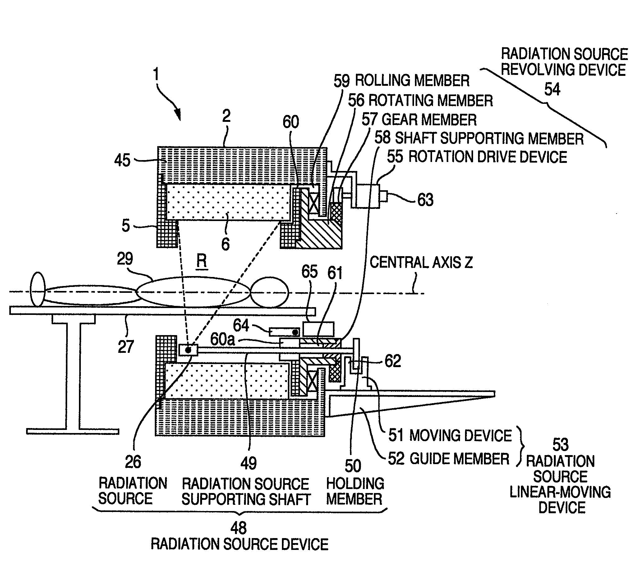
[0069]A device for positron emission computed tomography 1 (PET device) which is a preferable embodiment of the present invention will be described using FIG. 3 to FIG. 10. FIG. 3 is a schematic configuration diagram of the device for positron emission computed tomography of the embodiment. As shown in FIG. 3, the PET device of this embodiment comprises an imaging device 2, a bed 27 for supporting the patient 29 who is a subject, the data processing device 30, and the display device 33.

[0070]The imaging device 2 includes a housing 45 (see FIG. 6) surrounding a measurement space R, and a plurality of detector units 6 (see FIG. 4 and FIG. 6) arranged so as to surround the measurement space R.

[0071]FIG. 7 is an explanatory view when the detector unit is attached to the imaging device. The detector unit 6 is arranged surrounding the measurement space R and held by a unit supporting member 3 installed in the housing 45. These detector units 6 are inserted in a plurality of openings 4, wh...


PUM


Abstract

A first γ-ray generating in a body, caused by a PET pharmaceutical, and a second γ-ray emitted from a γ-ray source and transmitting through the body are detected with a radiation detector. The emission image information (E image information), E0, E1 and E2, at each of patient motion phases, 0, 1 and 2, which divided a cardiac beat and respiration period, are prepared by using each information obtained from the detected first γ-ray. The transmission image information (T image information), T0, T1 and T2, at each of patient motion phases, 0, 1 and 2, respectively, are prepared, by using each information obtained from the detected second γ-ray. Relative displacements, ([F10], [F20]), are determined by superimposing, on T image information T0, other T image information, T1 and T2. The E image information, E1, E2 are superimposed on the E image information E0, by using this relative displacement.

Description

BACKGROUND OF THE INVENTION[0001]The present invention relates to an image generation method using an image processing device.[0002]In recent years, representative ones of a radiation image diagnostic device, which non-invasively obtains image information in the body of a subject by applying a radiation measuring technique, include nuclear medicine diagnostic devices, such as a device for positron emission computed tomography (hereinafter, referred to as a PET device) and a device for single photon emission computed tomography (hereinafter, referred to as a SPECT device), and an X-ray CT scanner (hereinafter, referred to as a CT device).[0003]These radiation image diagnostic devices measure a detected physical quantity as an integrated value in the radiation traveling direction, and reconstruct tomographic image information using the physical quantity at each position in the body of a subject, respectively, based on this integrated value. In the X-ray CT scanner, an X-ray source is ...

Claims


Application Information

Patent Timeline
Patent Type & Authority Applications(United States)
IPC IPC(8): A61B6/00G06K9/00H05G1/60
CPCG06T11/008A61B6/037G06T2211/412
Inventor TAKEUCHI, WATARUKOBASHI, KEIJITAKAHASHI, ISAO
Owner HITACHI LTD
Why Eureka
Try Eureka