Image forming apparatus and method

a technology of forming apparatus and fixing roller, which is applied in the direction of electrographic process apparatus, instruments, optics, etc., can solve the problems of above-mentioned fixing system, consuming significant amount of energy, and requiring a relatively long time period to increase the temperature of the fixing roller

Inactive Publication Date: 2009-10-01
RICOH KK
View PDF43 Cites 26 Cited by
  • Summary
  • Abstract
  • Description
  • Claims
  • Application Information

AI Technical Summary

Problems solved by technology

However, such a fixing device simply including a heat applying system of the fixing roller consumes significant amount of energy.
Because, fixing energy largely relies on heat as a problem.
In addition, it especially takes a relatively long time period to increase temperature of the fixing roller suitable for fixing after a power is supplied to an image forming apparatus.
Further, the above-mentioned fixing system has some disadvantages when employed in an image forming apparatus capable of feeding sheets at a high line speed.
First, since the heat and pressure are simultaneously applied to the toner on the recording member at the nip, a sufficient nipping time period is hardly provided not to cause a fixing error.
Thus, when the above-mentioned fixing system is applied to the high-speed machine running at the high-line speed, fixing temperature and pressure of the fixing roller need to be high and large to handle, resulting in significant power consumption.
Further, since the high-speed machine necessarily employs a fixing roller having a large diameter to obtain a nipping time period or the like, calorie increases so that power consumption further increases.
Further, since heat excessive for toner fixing is applied to a non-image area on the recording member, curl or the other undesired phenomena occur on the recording member.
However, according to these configurations, since toner is heated by the magnetic field generation source via the fixing roller or the like serving as a heat-receiving member, heat efficiency is low and consumption of energy increases.

Method used


Image

  • Image forming apparatus and method
  • Image forming apparatus and method
  • Image forming apparatus and method

Examples


first embodiment

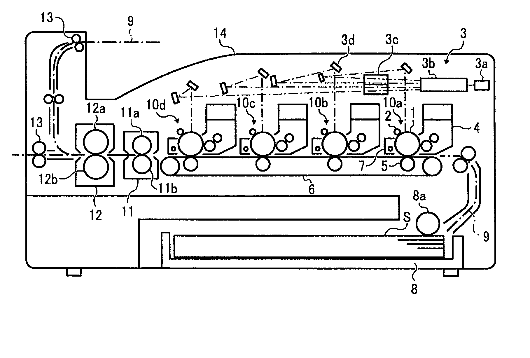
[0079]Referring now to the drawings, wherein like reference numerals and marks designate identical or corresponding parts throughout several figures, in particular in FIG. 1, the first embodiment is described. As shown, a versatile image forming apparatus is provided and includes fixing devices arranged in parallel employing heat and pressure applying systems capable of using toner and a recording member for a heat fixing system while suppressing energy consumption. The image forming apparatus can increase a brilliance performance of a toner surface and obtain an almost photographic quality saving the energy. Further, the image forming apparatus is capable of selectively using a pressure applying system in accordance with a necessity of brilliance for a sheet either manually or automatically.

[0080]In FIG. 1, four image formation sections 10a to 10d are arranged along a conveyance belt 6 (hereinafter referred to as a transfer belt 6) that carries and conveys a sheet like recording me...

second embodiment

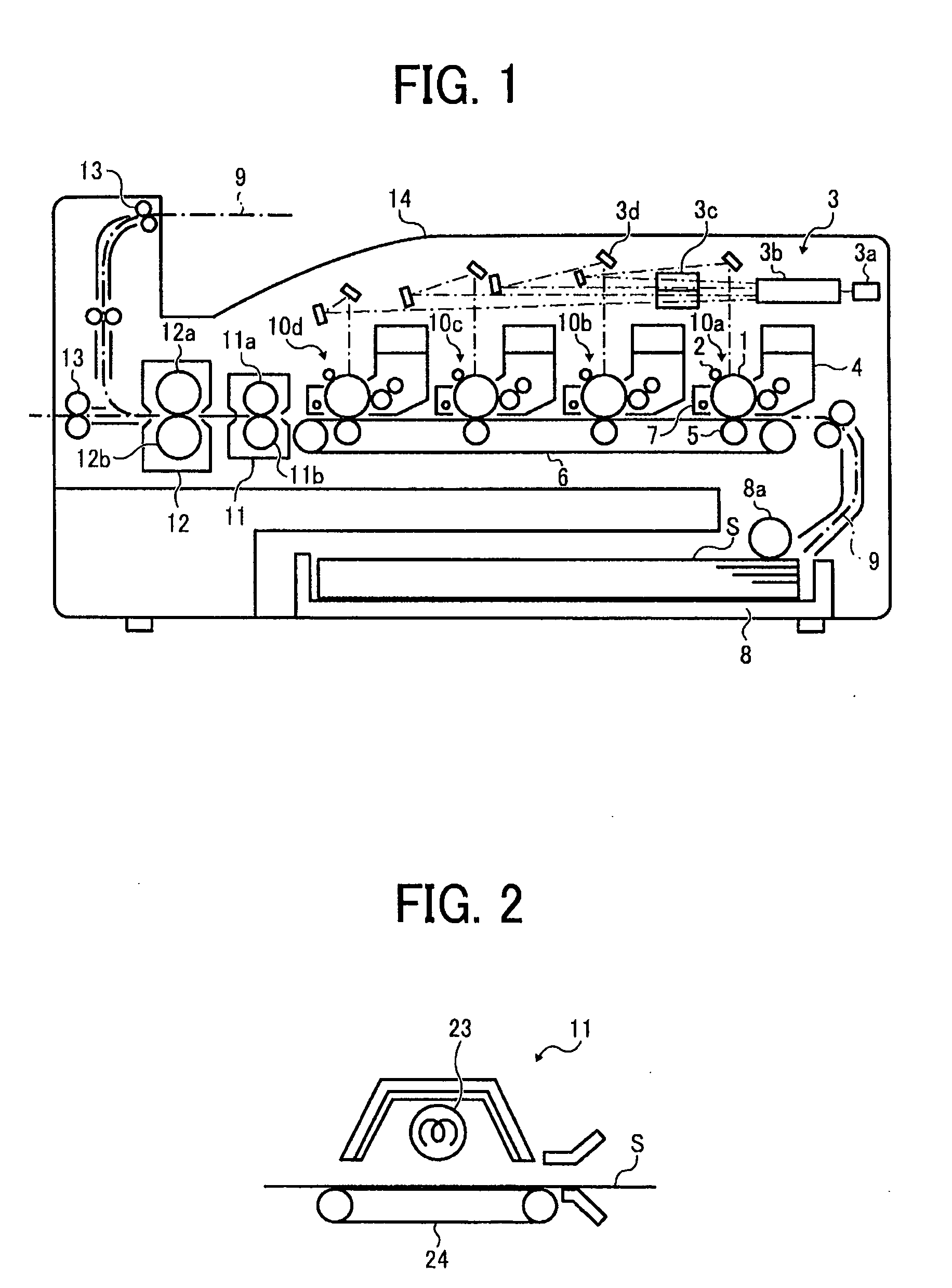
[0090]Further, the heat-applying device 11 can employ an oven system that applies radiation heat as shown in FIG. 2. Specifically, the toner does not contact the heat source, and heats the toner on the recording member S by means of the radiation heat from the heat source 23 as mentioned in the second embodiment in detail. Thus, the recording member S is conveyed by the conveyance belt 24 omitting a separation step of separating from the roller or the like.

[0091]According to this embodiment, since the second device 12 is arranged downstream of the first fixing device 11 in the recording medium conveyance direction, a highly brilliant image can be obtained by passing through the smoothing step. Since the heat-applying device 11 serves as the first fixing device for softening the toner while applying heat thereto more than a melting point of the toner, the toner is effectively softened. Further, since the pressure applying device 12 serves as the second fixing device for smoothing the...

third embodiment

[0122]Now, a third embodiment is described with reference to FIG. 20. In this embodiment, fixing devices employing a heat and pressure applying systems, respective, are arranged in parallel to provide a versatile configuration that uses toner and plain paper as generally used in a heat fixing system while decreasing a start up time period and saving energy. Further, both of a transfer and heat applying steps are provided along the recording member conveyance belt so as to soften the toner to be carried on the conveyance belt before a recording member is separated there from, so that an image forming apparatus can suppress toner scatter and image disturbance at the time of the toner separation. Further, the pair of pressure applying rollers employing the pressure applying system of the fixing device are separated to suppress a problem of a cut or the like caused by contact of those.

[0123]Specifically, in FIG. 20, the fundamental configuration and an operation of the image forming app...


PUM


Abstract

An image forming apparatus includes a first fixing device that applies heat to a non fixed toner image and a second fixing device arranged downstream of the first fixing device, which applies pressure and fixes the non-fixed toner image onto a recording member.

Description

CROSS REFERENCE TO RELATED APPLICATION[0001]This application claims priority under 35 USC §119 to Japanese Patent Application No. 2008-094993, filed on Apr. 1, 2008, the entire contents of which are herein incorporated by reference.BACKGROUND OF THE INVENTION[0002]1. Field of the Invention[0003]The present invention relates to an image forming apparatus, such as a copier, a printer, a plotter, a facsimile, and a complex machine combining these device, etc., having a unique fixing system.[0004]2. Discussion of the Background Art[0005]Conventionally, in an image forming apparatus, such as a copier, a printer, etc., a fixing device is included to fix a toner image transferred onto a recording member. To avoid insufficient fixing, various fixing systems have been developed. In these days, a heat-applying roller that applies heat from a heat-applying source is generally used as a fixing roller, while a pressure-applying roller is provided opposing the fixing roller to form a nip in a hea...

Claims


Application Information

Patent Timeline
Patent Type & Authority Applications(United States)
IPC IPC(8): G03G15/20G03G13/20
CPCG03G15/2007G03G2215/2006G03G15/2064
Inventor ISHIKAKE, SATORUMOCHIZUKI, MANABUKUROTORI, TSUNEOARAI, YOSHIHIRO
Owner RICOH KK
Why Eureka
Try Eureka