Electrochemical Device

a technology of electrochemical devices and electrodes, which is applied in the direction of cell components, final product manufacturing, sustainable manufacturing/processing, etc., can solve the problems of explosion or ignition, short circuit, and inability to always act stably of safety valves such as those mentioned above, so as to improve safety of electrochemical devices in abnormally high temperature atmospheres, the effect of easy adjustment of resistance values

Active Publication Date: 2009-10-01
TDK CORPARATION
View PDF3 Cites 28 Cited by
  • Summary
  • Abstract
  • Description
  • Claims
  • Application Information

AI Technical Summary

Benefits of technology

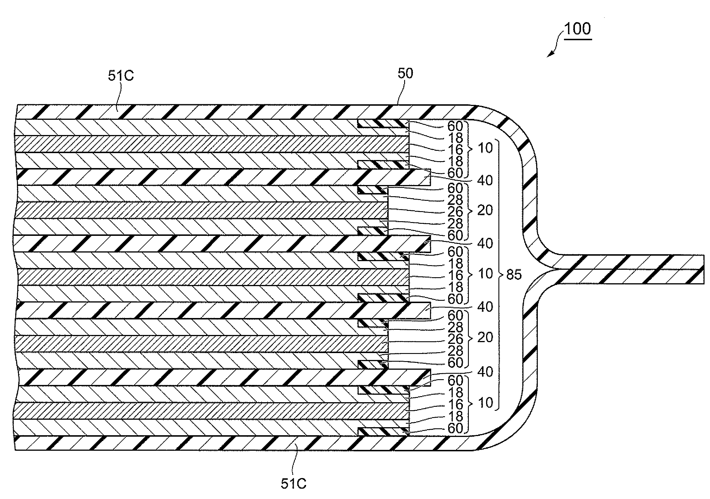
[0015]Preferably, in the electrochemical device in accordance with the present invention, the resistance control layer is a layer containing carbon black, a binder, and a ceramic particle. This makes it easier to adjust the resistance value of the resistance control layer in the thickness direction, so that a thin resistance control layer having a favorable resistance value can be formed, whereby the safety of the electrochemical device in abnormally high temperature atmospheres can farther be improved.
[0016]Preferably, the ratio of the content of the carbon black to that of the binder and ceramic particle in the resistance control layer is 1:99 to 10:90 in terms of mass ratio. When the contents of these components fall within the range mentioned above, a thin resistance control layer having a favorable resistance value can easily be formed, whereby the safety of the electrochemical device in abnormally high temperature atmospheres can further be improved.
[0017]It will also be preferred in the electrochemical device in accordance with the present invention if the resistance control layer is a layer made of a high-resistance metal material or a ceramic material. This also makes it easier to adjust the resistance value of the resistance control layer in the thickness direction, so that a thin resistance control layer having a favorable resistance value can be formed, whereby the safety of the electrochemical device in abnormally high temperature atmospheres can further be improved.
[0018]Preferably, in the electrochemical device in accordance with the present invention, the separator is constituted by a polyolefin, a polyamide imide having a surface coat

Problems solved by technology

However, safety valves such as those mentioned above do not always act stably.
Also, if outer packages are inflated by internal pressures so that pressures apply to electrode matrixes before the safety valves act

Method used


Image

  • Electrochemical Device
  • Electrochemical Device
  • Electrochemical Device

Examples


example 1

[0090]Making of Negative Electrode

[0091]A negative electrode was made by the following procedure. First, 90 parts by mass of mesocarbon microbeads (MCMB) (manufactured by Osaka Gas Co., Ltd.) and 1 part by mass of graphite (product name: KS-6 manufactured by Lonza) as a negative electrode active material, 2 parts by mass of carbon black (product name: DAB manufactured by Denki Kagaku Kogyo, K.K.) as a conductive auxiliary agent, and 7 parts by mass of polyvinylidene fluoride (product name: Kynar 761 manufactured by Atofina) as a binder were mixed and dispersed, and then an appropriate amount of N-methylpyrrolidone (NMP) as a solvent was added thereto, so as to adjust viscosity, thereby making a slurry-like negative electrode coating liquid.

[0092]Subsequently, a copper foil (having a thickness of 20 μm) as a negative electrode current collector was prepared, the negative electrode coating liquid was applied to both faces of the copper foil and dried, so as to form negative electrode ...

example 2

[0103]After mixing and dispersing 3 parts by mass of carbon black (product name: DAB manufactured by Denki Kagaku Kogyo, K.K.), 40 parts by mass of polyvinylidene fluoride (product name: Kynar 761 manufactured by Atofina) as a binder, and 57 parts by mass of zirconia oxide particles (product name: Zirconia Oxide, manufactured by Kojundo Chemical Lab. Co., Ltd., having an average particle size of 1 μm), an appropriate amount of N-methylpyrrolidone (INM) as a solvent was added thereto, so as to adjust viscosity, thereby making a slurry-like resistance control layer coating liquid. Except that the resistance control layers of the negative and positive electrodes were produced by using this resistance control layer coating liquid, a lithium-ion secondary battery was made as in Example 1.

example 3

[0104]After mixing and dispersing 2 parts by mass of carbon black (product name: DAB manufactured by Denki Kagaku Kogyo, K.K.), 40 parts by mass of polyvinylidene fluoride (product name: Kynar 761 manufactured by Atofina) as a binder, and 58 parts by mass of zirconia oxide particles (product name: Zirconia Oxide, manufactured by Kojundo Chemical Lab. Co., Ltd., having an average particle size of 1 μm), an appropriate amount of N-methylpyrrolidone (AMP) as a solvent was added thereto, so as to adjust viscosity, thereby making a slurry-like resistance control layer coating liquid. Except that the resistance control layers of the negative and positive electrodes were produced by using this resistance control layer coating liquid, a lithium-ion secondary battery was made as in Example 1.


PUM


Abstract

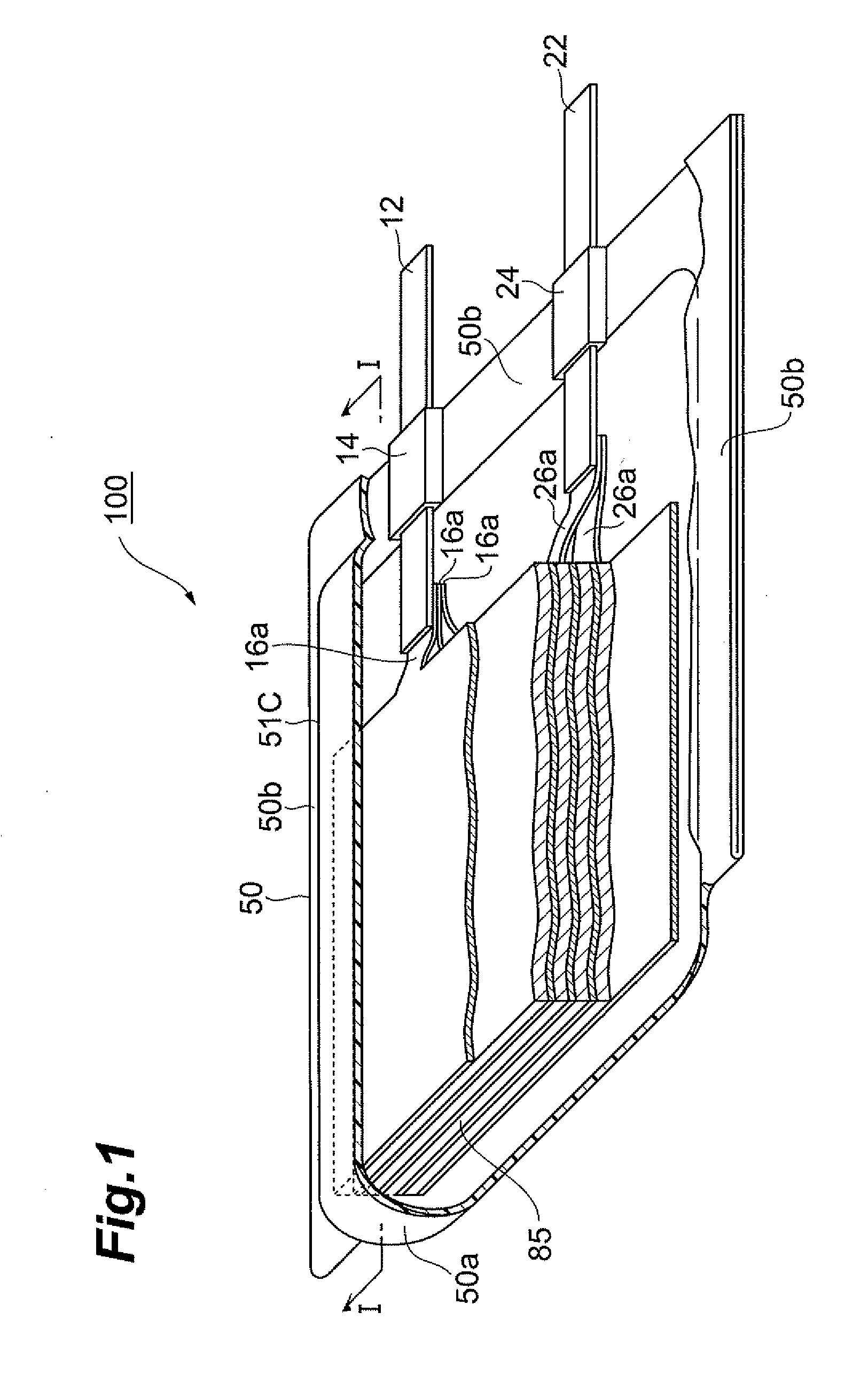
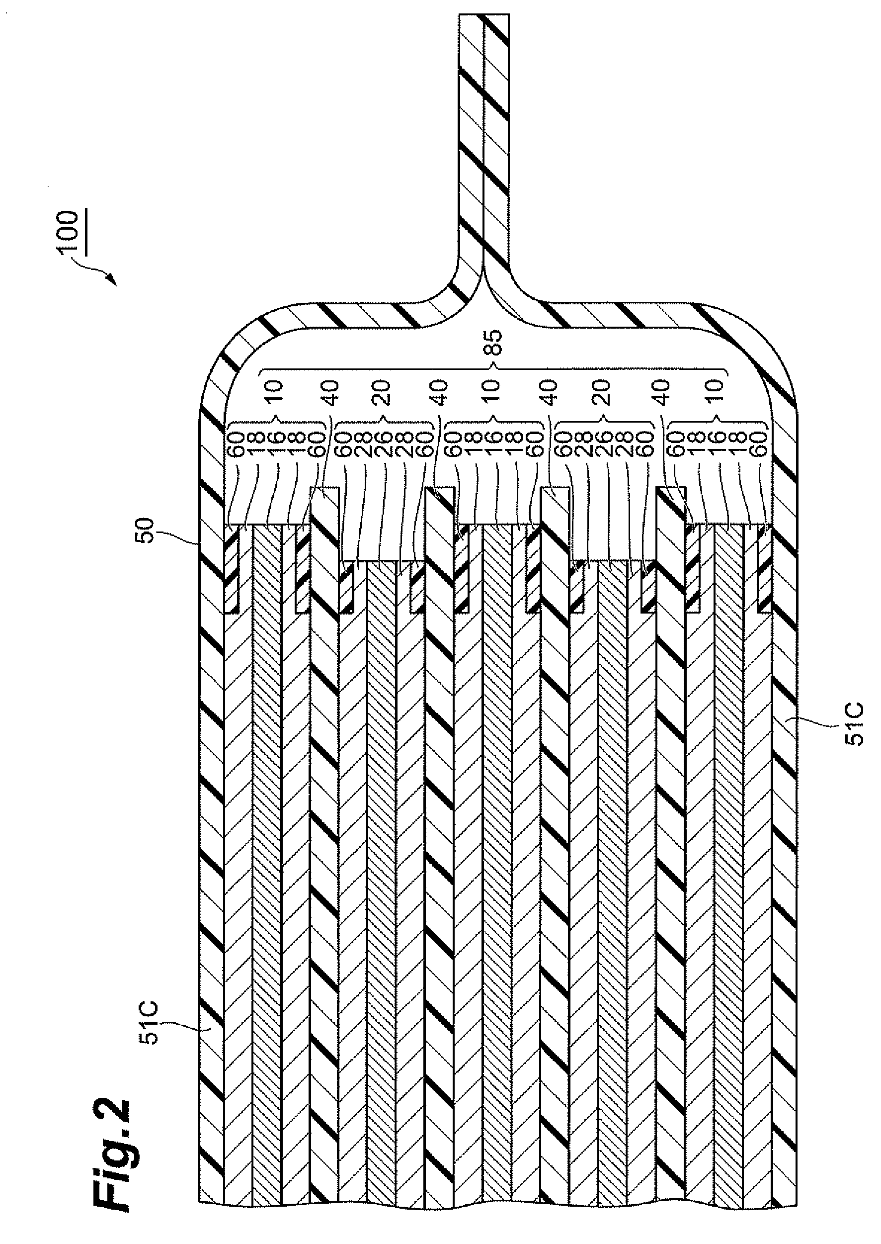
An electrochemical device having an electrode matrix including a multilayer structure laminating positive and negative electrodes with a separator interposed therebetween; wherein at least one of the positive and negative electrodes has a resistance control layer at least at an edge part exposed when the separator thermally shrinks on a surface on the separator side; and wherein the resistance control layer has a resistance value as a total resistance value of the electrode matrix falling in such a range that an estimated internal short circuit current between the positive and negative electrodes is equivalent to 0.09 C to 1 C.

Description

BACKGROUND OF THE INVENTION[0001]1. Field of the Invention[0002]The present invention relates to an electrochemical device.[0003]2. Related Background Art[0004]As portable electronic devices have been becoming widespread, there have been increasing demands for lightweight, small-size electrochemical devices which can continuously be driven for a long time, such as secondary batteries. While conventional secondary batteries used metal outer cans, it has become possible to reduce the battery weight by employing thin, lightweight films for outer bags, as typified by lithium polymer batteries, thereby increasing the degree of freedom in designing.[0005]When some abnormalities happen in a battery using such a film as its outer bag, gases may be generated or, in the worst case, ignition may occur depending on kinds of electrolytes in use. While chargers are set such as to stop charging when reaching a predetermined time or voltage, electrochemical devices will be overcharged if the chargi...

Claims


Application Information

Patent Timeline
IPC IPC(8): H01M2/16H01M2/02H01G11/10H01G11/14H01G11/22H01G11/52H01M4/02H01M4/13H01M10/04H01M10/0585H01M50/414H01M50/466
CPCH01M2/162H01M2/1653H01M2/1673H01M2/18Y02E60/122H01M4/624H01M10/4235H01M2004/024H01M4/13Y02E60/10H01M50/44H01M50/46Y02P70/50H01M50/466H01M50/414
Inventor NAOI, KATSUONISHIZAWA, KENJIKOUGO, MITSUO
Owner TDK CORPARATION
Why Eureka
Try Eureka