Power plant

a power plant and power technology, applied in the field of power plants, can solve the problems of further reducing the driving efficiency of the power plant, the inability to obtain a sufficient electric power-generating efficiency, and the reduction of the power plant's driving efficiency, and achieve the effect of increasing the torqu

Active Publication Date: 2009-10-01
HONDA MOTOR CO LTD
View PDF11 Cites 24 Cited by
  • Summary
  • Abstract
  • Description
  • Claims
  • Application Information

AI Technical Summary

Benefits of technology

[0062]With this arrangement, the first rotor corresponding to the sun gear or the ring gear of the planetary gear unit is connected to the engine. Therefore, as already described in the operation by claim 11, in transmitting the power from the engine to the driven part via the first and second rotors, by interrupting the connection between the one rotor, i.e. the first rotor and the driven part using th...

Problems solved by technology

As described above, in the conventional power plant, since during operation in the torque circulation mode, the transmission of power from the engine and the generator-motor to the drive wheels is carried out necessarily via the planetary gear unit, and hence due to power transmission loss caused by mechanical mating of teeth of gears at the planetary gear unit, the driving efficiency of the power plant is reduced.
Further, the power from the generator-motor is necessarily transmitted via the stepless transmission in addition to the planetary gear unit, and hence the driving efficiency of the power plant is further reduced due to power transmission loss at the stepless transmission.
Further, during the operation in the torque circulation mode, also when electric power is generated by the generator-motor using the power from the drive wheels, the transmission of power from the drive wheels to the generator-moto...

Method used


Image

  • Power plant
  • Power plant
  • Power plant

Examples


first embodiment

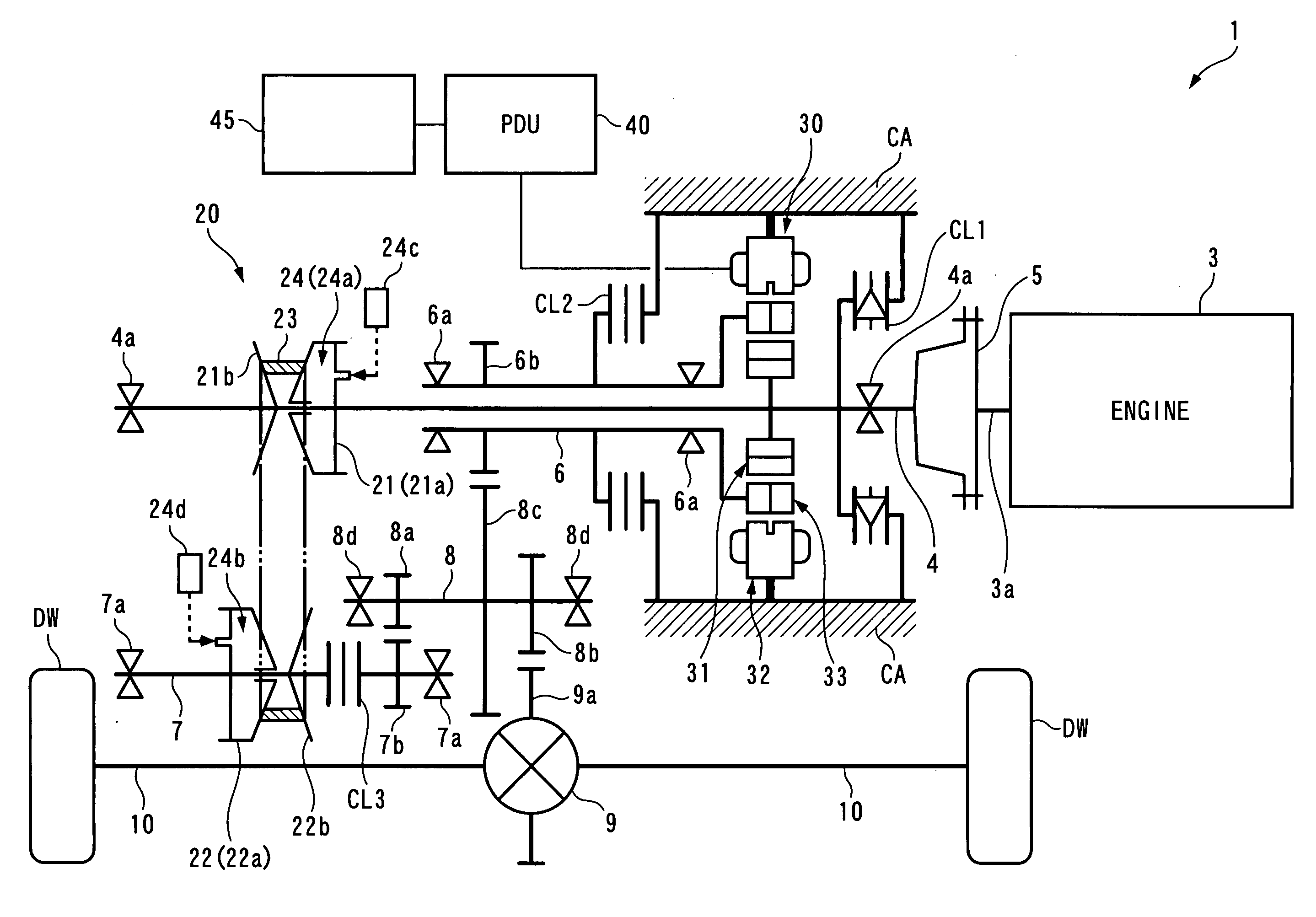
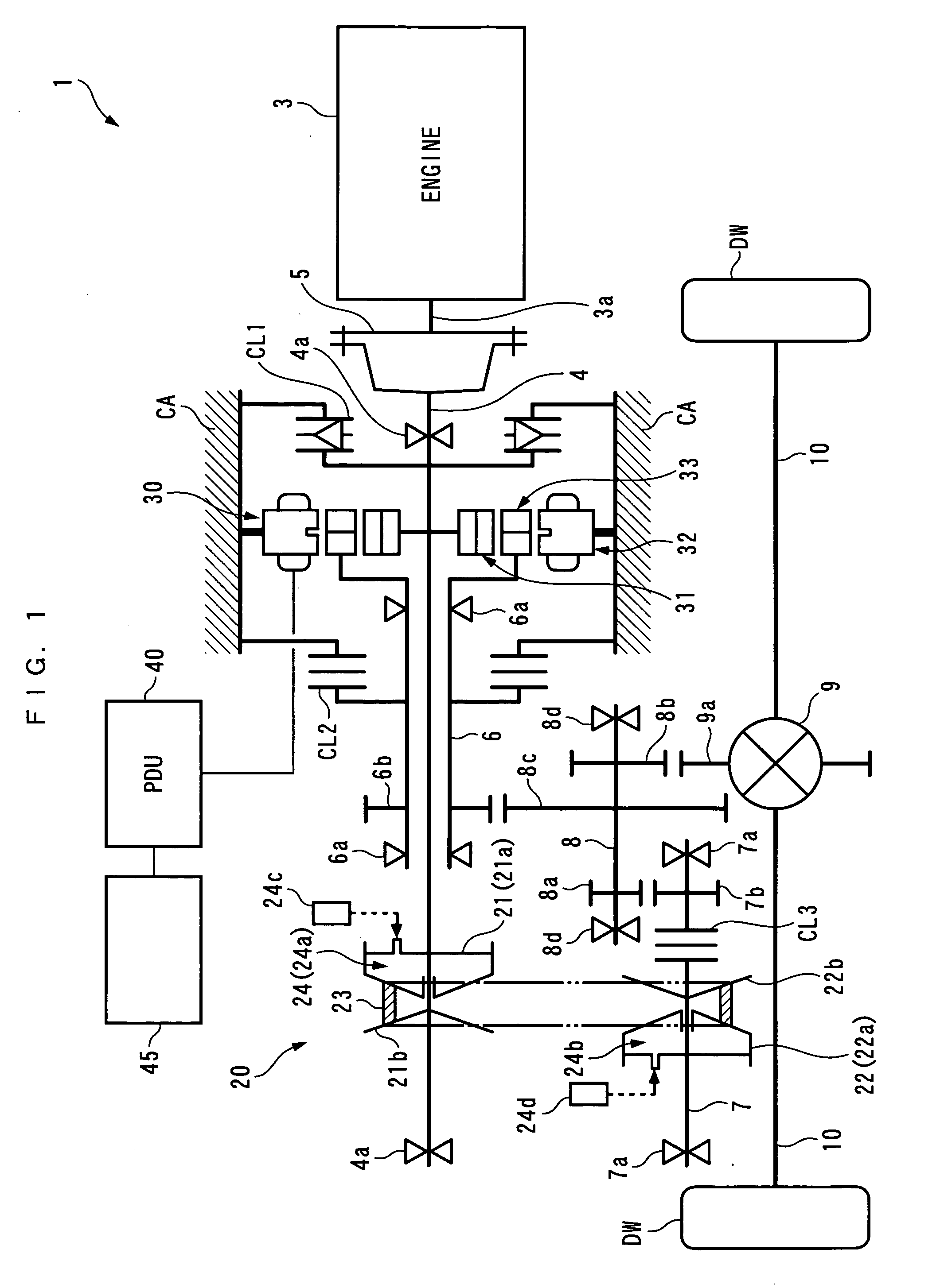
[0121]The present invention will now be described in detail with reference to the drawings showing a preferred embodiment thereof. It should be noted that in the figures, hatching for portions illustrating cross-sections are omitted for convenience. FIG. 1 schematically shows a power plant 1 according to the present embodiment. The power plant 1 is for driving drive wheels DW and DW (driven parts) of a vehicle (not shown), and includes an internal combustion engine 3 and a generator-motor 30 as power sources, a stepless transmission 20 (first transmission) for transmitting a driving force to the drive wheels DW and DW, a differential gear mechanism 9, and drive shafts 10 and 10.

[0122]The internal combustion engine (hereinafter referred to as “the engine”) 3 is e.g. a gasoline engine, and has a crankshaft 3a (output shaft) to which is connected a first main shaft 4 via a flywheel 5. The first main shaft 4 is supported by a bearing 4a such that it is rotatable concentrically with the ...

second embodiment

[0257]A gear 4b is fixed to the first main shaft 4. The gear 4b is in mesh with the gear 7b fixed to the aforementioned auxiliary shaft 7. The gear ratio between the gears 4b and 7b is set to 1:1, for example. Further, differently from the second embodiment, the idler shaft 8 is not provided with the above-described first idler gear 8a, and the clutch CL3 has an input shaft and an output shaft thereof directly connected to the auxiliary shaft 7 and the idler shaft 8, respectively. The degree of engagement of the clutch CL3 is controlled by the ECU 2, whereby the connection between the auxiliary shaft 7 and the idler shaft 8 is established and interrupted. Furthermore, the gear ratio between the gear 6b and the third idler gear 8c is set to 1:1, for example.

[0258]With the above arrangement, when the clutch CL3 is engaged, the crankshaft 3a and the first rotor 31 are mechanically connected to the drive wheels DW and DW via the first main shaft 4, the gear 4b, the gear 7b, the auxiliar...

fifth embodiment

[0326]First, a description will be given of the operation during the operation of the engine 3 and at the same time during traveling of the vehicle. After the above-mentioned ENG-driven standing start, the speed of the power transmitted from the engine 3 to the drive wheels DW and DW during disengagement of the clutch CL3 is steplessly changed by controlling the magnetic field rotational speed VMF. That is, similarly to the fifth embodiment, the generator-motor 30 functions as a stepless transmission. Hereafter, this point will be described with reference to FIGS. 55 and 56.

[0327]As is apparent from the above-described connecting relationship, the second rotor rotational speed VR2 is equal to the engine speed NE, and the first rotor rotational speed VR1 is equal to the vehicle speed VP if there is no change in speed by the differential gear mechanism 9. Therefore, the relationship between the magnetic field rotational speed VMF, the first and second rotor rotational speeds VR1 and V...


PUM


Abstract

To provide a power plant which is capable of improving the driving efficiency and electric power-generating efficiency thereof. A first transmission 20 is connected between the output shaft 3a of an internal combustion engine 3 and driven parts DW and DW, which are connected to each other. A generator-motor 30 includes a stator 32 for generating magnetic fields and first and second rotors 31 and 33, and carries out energy input and output between the stator 32 and the first and second rotors 31 and 33 during generation of rotating magnetic fields. Along with the energy input and output, the rotating magnetic fields and the first and second rotors 31 and 33 rotate while maintaining such a linear speed relationship that the difference between the rotational speed of the magnetic fields and that of the second rotor 33, and the difference between the rotational speed of the second rotor 33 and that of the first rotor 31 are equal to each other. One of the first and second rotors 31 and 33 is connected between the output shaft 3a of the engine 3 and the first transmission 20, and the other to the driven parts DW and DW.

Description

BACKGROUND OF THE INVENTION[0001]1. Field of the Invention[0002]The present invention relates to a power plant for driving a driven part, and more particularly to a power plant including an internal combustion engine and a generator-motor as power sources.[0003]2. Description of the Related Art[0004]Conventionally, as the power plant of this kind, one disclosed in Patent Literature 1 is known. This power plant is for driving drive wheels of a vehicle, and is equipped with an internal combustion engine and a generator-motor as power sources, and a stepless transmission and a planetary gear unit for transmitting power to the drive wheels. The planetary gear unit is a general single pinion type that has a sun gear, a ring gear, and a carrier, and the sun gear and the ring gear are connected to the drive wheels via a high clutch and a low clutch, respectively. The engine is connected to the carrier via a main shaft, and the main shaft is connected to an input pulley of the stepless tran...

Claims


Application Information

Patent Timeline
IPC IPC(8): B60W10/04B60K6/26B60K6/365B60W20/00B60L50/16
CPCB60K6/26Y02T10/6217B60K6/448B60K6/48B60K6/543B60K6/547B60L11/14B60W10/02B60W10/06B60W10/08B60W20/00F16H37/0846H02K7/006H02K7/116H02K16/02H02K51/00H02P2207/03Y02T10/6221Y02T10/6243Y02T10/6286Y02T10/641Y02T10/642Y02T10/7077B60L11/123B60K6/365B60L50/61B60L50/16Y02T10/62Y02T10/64Y02T10/7072Y02T10/70B60K6/44B60W10/101B60W20/30
Inventor ABE, NORIYUKIAKUTSU, SHIGEMITSU
Owner HONDA MOTOR CO LTD
Why Eureka
Try Eureka