
Balloons and balloon catheter systems for treating vascular occlusions

Inactive Publication Date: 2009-10-01
ENDOCROSS
View PDF99 Cites 104 Cited by
  • Summary
  • Abstract
  • Description
  • Claims
  • Application Information

AI Technical Summary

Benefits of technology

[0010]In certain embodiments, the present invention provides an occlusion-crossing system that may minimize trauma to the body passage wall.
[0011]In certain embodiments, the present invention provides a vascular occlusion-crossing system that will minimize trauma to the vascular wall.
[0012]In certain embodiments, the present invention provides a CTO-crossing system that will minimize trauma to the vascular wall.
[0013]In certain embodiments, the present invention provides a balloon that is designed so that flipping backward, bending, and / or undesired and / or premature collapse of proximal tapers is reduced, delayed, or avoided.
[0014]In certain embodiments, the present invention provides a balloon that is designed so that collapsing and / or bending of the balloon is reduced, delayed, or avoided.
[0017]In certain embodiments, the present invention provides a balloon preferably reduces or minimizes trauma to the vascular wall or wall of other body passage is provided.

Problems solved by technology

However, PCI of cases of CTO have historically posed problems, with lower success rates (40 to 80 percent-average 60 percent), higher equipment costs, and a higher restenosis rate.
Conventional intervention tools such as angioplasty balloons are often too flexible or blunt to cross highly stenosed lesions such as CTOs, which often contains extremely hard, calcified tissue that may form an impenetrable barrier to the advancement of a guidewire therethrough.
In view of the great difficulties encountered in attempting to properly position a guidewire across the stenosis, conventional guided atherectomy or dilatation devices such as cutting elements and balloons cannot be used to cross the lesion as long as a guidewire was not inserted through the lesion since they rely on complete wire crossability.
A further problem associated with the use of conventional devices is the risk of perforating the blood vessel being treated.
For example, a guidewire or cutting tool, when advanced, may cause dissection of the tissues of the arterial wall instead of the occlusion, thereby creating a false lumen and possibly perforating the artery.
Another reason that conventional types of apparatus are typically ineffective in treating total or near total occlusions is that conventional balloon catheter shafts and guidewires do not perform well under the compressive loading and torque loading that are required in order to advance such devices across a CTO lesion.

Method used


Image

  • Balloons and balloon catheter systems for treating vascular occlusions
  • Balloons and balloon catheter systems for treating vascular occlusions
  • Balloons and balloon catheter systems for treating vascular occlusions

Examples


first main embodiment

Balloon Catheter Having Oscillating Catheter Shaft Distal Tip

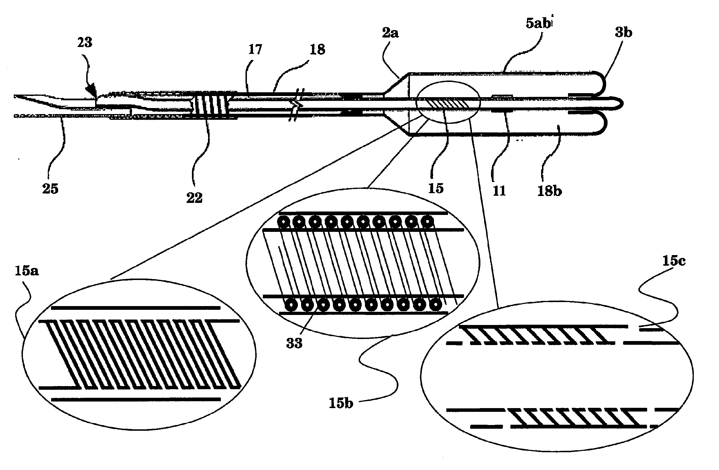
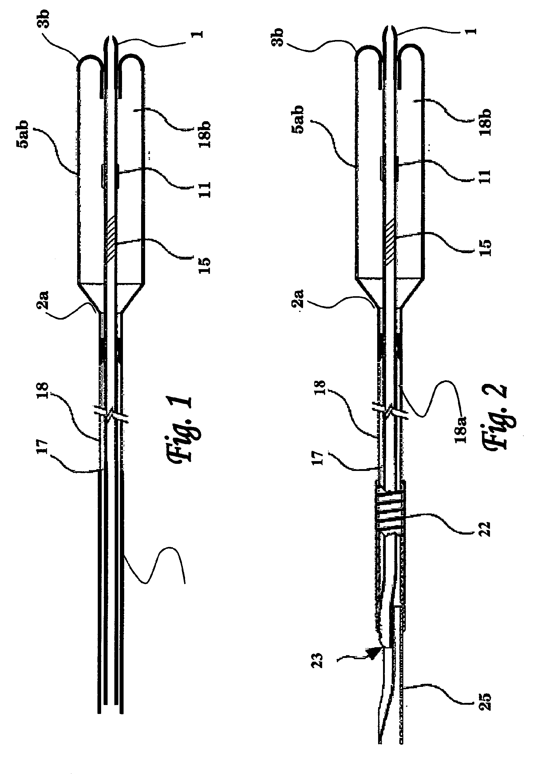
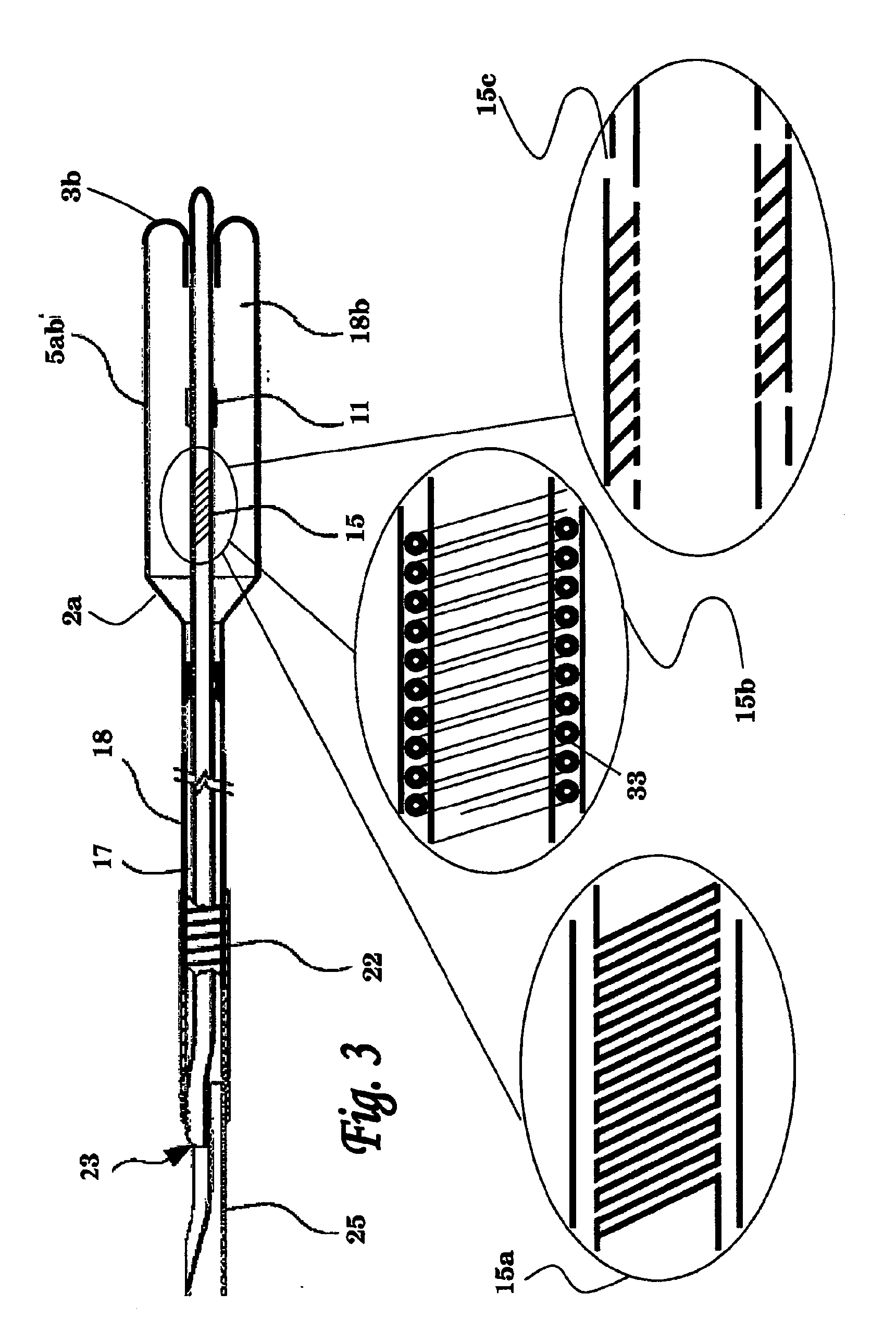
[0064]FIG. 1 schematically illustrates an over the wire implementation of the balloon catheter of the invention. This balloon catheter implementation comprises an outer shaft 18, inner shaft 17 passing thereinside, and a balloon 5ab. The lumen of inner shaft 17 may be used for passing a guide wire thereinside, which may be introduced via its proximal opening (e.g., 12 in FIGS. 7A-7F).

[0065]In the pre-charged embodiment shown in this figure, balloon 5ab has a conical proximal end 2a which tapers proximally towards its annular attachment area on the outer surface of the distal end portion of outer shaft 18, and a rounded distal end 3b which is obtained by folding the distal end of balloon 5ab proximally inwardly and by attaching the outer surface of its distal end portion to an annular attachment area on the outer surface of the distal end portion of inner shaft 17. Other types of balloon attachment (resulting in either pre-...

second main embodiment

Balloon Catheter Having Oscillating Guide Wire Immobilized within Catheter Shaft

[0106]In this second main embodiment of the invention, the balloon catheter system comprises a guidewire (also referred to herein as a ramming tool) immobilized within an inner catheter shaft lumen, wherein the balloon catheter is capable of delivering rapid motion to the guidewire passing therein. The in vivo application of such rapid motion to, or adjacent to, an occlusion formed in a body organ or pathway is effectively utilized for fracturing the occluding matter and for perforating a passage thereinside, that may allow crossing and / or removing the occluding matter.

[0107]The balloon catheter of the invention is preferably constructed from concentric tubes having an inflatable member, such as a balloon, attached to their distal ends. The inflatable member can be a sleeve having tapering ends that can be sealably attached to the distal end portions of the inner and outer tubes of the catheter device, s...


PUM


Abstract

A balloon catheter system for the intraluminal advancement of conventional guidewires beyond partially or fully occluded or stenosed lesions in body passages, such as CTOs in the vasculature, is provided. Balloons are provided. In certain embodiments of the invention, a balloon having relatively thickened proximal tapers is provided. In certain embodiments of the invention, balloons having a tapered midsection are provided. The balloons are preferably useful with crossing balloon catheter systems. In certain embodiments of the invention, the balloons preferably reduce or minimize trauma to the vascular wall or wall of other body passage in which it is used.

Description

[0001]This application claims the benefit of U.S. Provisional Patent Application No. 60 / 960,930, filed Oct. 22, 2007, which is incorporated by reference herein in its entirety. This application also incorporates the following applications by reference in their entireties: U.S. Provisional Patent Application No. 60 / 726,180, filed Oct. 14, 2005; U.S. Provisional Patent Application No. 60 / 800,035, filed May 15, 2006; U.S. patent application Ser. No. 11 / 546,571 filed Oct. 12, 2006; International Application PCT / IB2006 / 002958, filed Oct. 13, 2006; and International Application PCT / IL2007 / 000590, filed May 14, 2007.FIELD OF THE INVENTION[0002]The present invention relates to balloon catheter devices and balloon catheter systems and methods of use thereof. More specifically, the present invention provides crossing balloon systems (CBS) for use in the treatment of occluded body passages and chronic total occlusion (CTO) and related conditions in blood vessels. The CBSs are preferably used i...

Claims


Application Information

Patent Timeline
IPC IPC(8): A61M25/10A61B17/22A61F2/958
CPCA61M25/1002A61M25/1006A61M2025/1061A61M25/104A61M25/1018A61M25/10188A61M2025/102A61M2025/1022A61M25/10181
Inventor LEVIT, ERANHIRSZOWICZ, ERAN
Owner ENDOCROSS
Learn More