Gas treatment apparatus

a gas treatment apparatus and gas treatment technology, applied in the direction of coatings, chemical vapor deposition coatings, metallic material coating processes, etc., can solve the problems of reducing the reflectivity affecting the heat transfer (heat radiation) toward the rear side of the shower head, and affecting the efficiency so as to prevent undesirable thermal decomposition, suppress the effect of the gas injection mechanism and suppress the decrease of the film forming ra

Inactive Publication Date: 2009-10-08
TOKYO ELECTRON LTD
View PDF4 Cites 30 Cited by
  • Summary
  • Abstract
  • Description
  • Claims
  • Application Information

AI Technical Summary

Benefits of technology

[0010]In view of the foregoing, the present invention provides a processing apparatus capable of suppressing a temperature rise of a gas injection mechanism such as a shower head and capable of reducing defects or nonuniformity of processing due to the temperature rise of the gas injection mechanism.
[0018]In accordance with the present invention, heat of the gas injection part is efficiently dissipated toward the atmosphere outside the processing vessel from the substantially entire circumference of the outer peripheral portion via the heat dissipating mechanism (or the heat dissipation member) . Accordingly, a temperature rise of the gas injection mechanism is effectively suppressed.
[0019]As a result, in a case of a film forming process that uses a thermal decomposition reaction of a processing gas supplied toward a target substrate on the mounting table from the gas injection mechanism, the gas injection mechanism can be maintained at a temperature level less than a decomposition temperature of the source gas. Accordingly, it is possible to prevent an undesirable thermal decomposition of the source gas in the gas injection mechanism or in a pipe connected thereto due to overheating of the gas injection mechanism before the source gas reaches the target substrate. Further, it is possible to suppress decrease in a film forming rate (increase in the processing time) and variation in the film thickness and quality due to decrease or deviation in the concentration of the source gas or the variation in the reflectivity of the gas injection mechanism by attachments of decomposed products thereto. Furthermore, it is possible to suppress occurrence of defective film due to attachments of the decomposed products to the target substrate after being peeled off from the gas introduction mechanism.

Problems solved by technology

However, if the flat gas diffusion space is present inside the shower head, the space impedes a heat transfer (heat radiation) toward the rear side of the shower head.
Particularly, with regard to the MOCVD method which uses the thermal decomposition of the source gas, an undesirable thermal decomposition reaction would take place inside the shower head or in a pipe upstream of the shower head if the temperature of the shower head increase over a thermal decomposition temperature of the source gas, resulting in a decrease in the concentration of the source gas supplied to the semiconductor wafer or a decrease in the reflectivity of the shower head due to an attachment of decomposed products of the source gas to the shower head.
In such cases, the temperature of the semiconductor wafer would be reduced, resulting in poor film formation.
Moreover, if the temperature of the shower head increases with a lapse of time as described above, it would cause a great deviation in film quality or composition.
Besides, if the decomposed products are separated from the surface of the shower head and stick to the semiconductor wafer as foreign substances, poor film formation would be resulted.

Method used


Image

  • Gas treatment apparatus
  • Gas treatment apparatus
  • Gas treatment apparatus

Examples


Embodiment Construction

[0027]Hereinafter, an embodiment of the present invention will be described in detail with reference to the accompanying drawings.

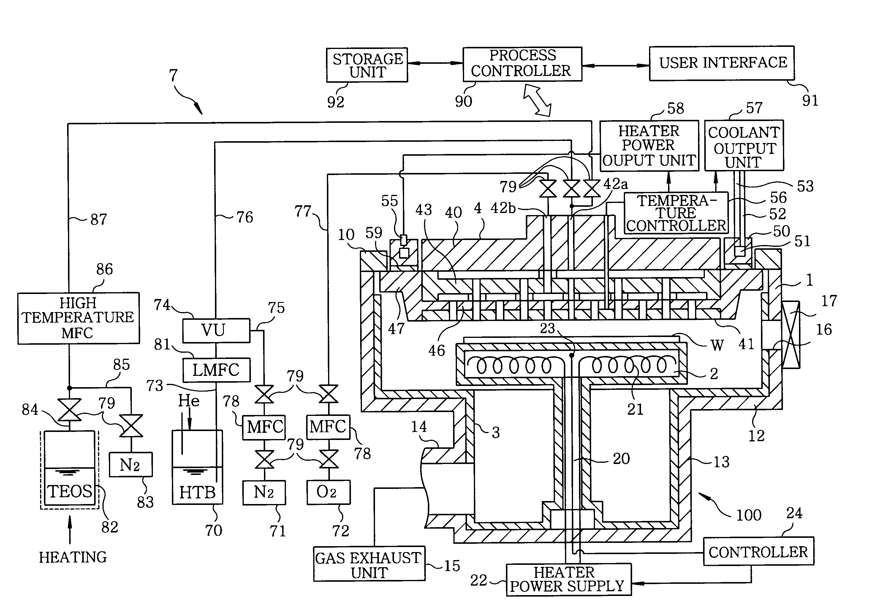
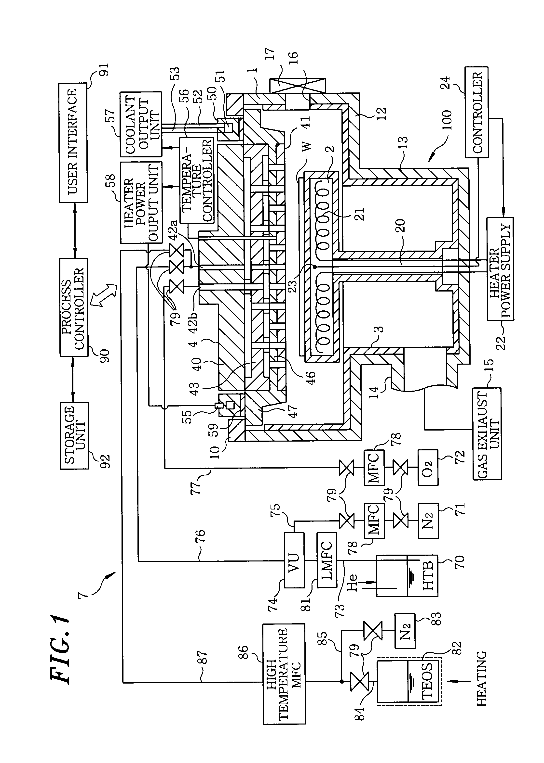
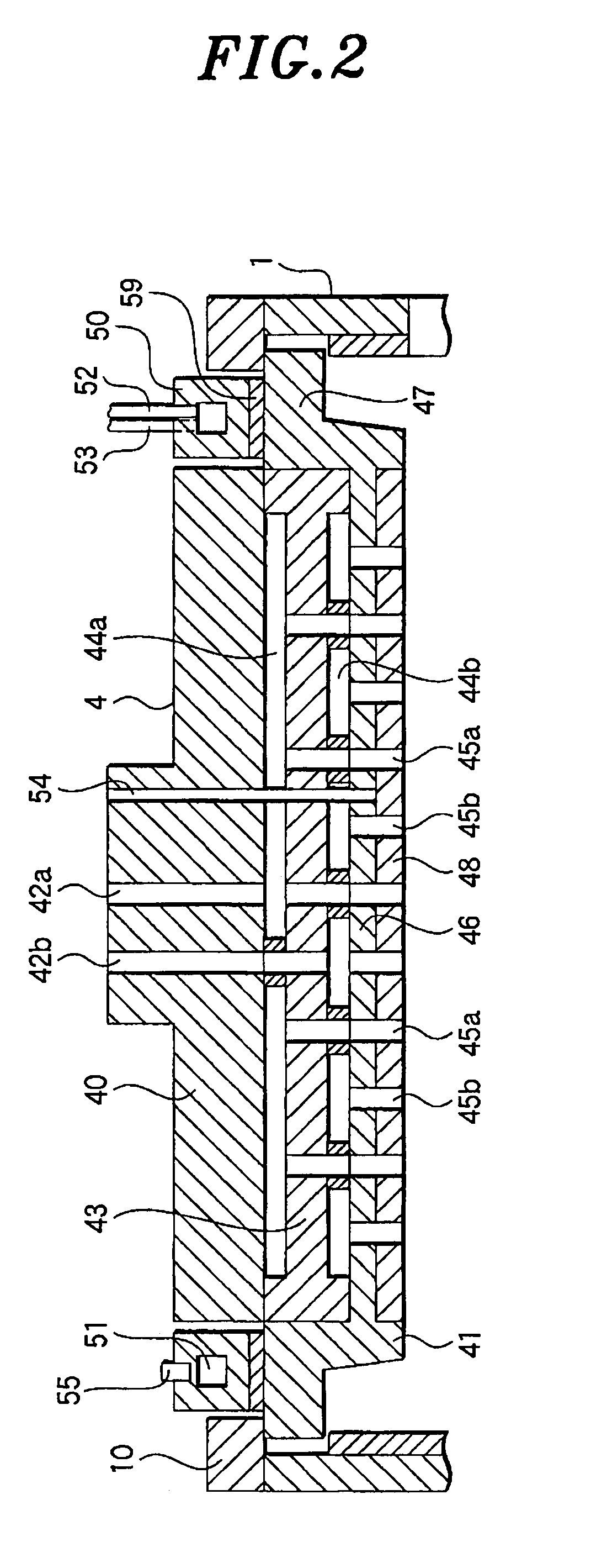
[0028]FIG. 1 is a cross sectional view showing a film forming apparatus as an example of a processing apparatus in accordance with an embodiment of the present invention. FIG. 2 sets forth a cross sectional view showing major parts of a chamber and a shower head of the film forming apparatus, and FIG. 3 depicts a cutaway perspective view of the chamber and the shower head.

[0029]The film forming apparatus 100 includes a substantially cylindrical chamber 1 which is configured as an airtight processing vessel. Inside the chamber 1, a mounting table 2 for mounting thereon a Si substrate (wafer) W to be processed is sustained on a cylindrical supporting member 20 disposed at a central bottom portion of the chamber 1. The mounting table 2 is made of ceramic such as AlN. Further, a heater 21 is embedded in the mounting table 2, and a heater power supply 22 is co...


PUM

PropertyMeasurementUnit
thicknessaaaaaaaaaa
thicknessaaaaaaaaaa
thicknessaaaaaaaaaa

Abstract

A film forming apparatus includes a chamber for accommodating a wafer; a mounting table arranged in the chamber to mount the wafer thereon; a shower head arranged to face the mounting table for injecting a processing gas into the chamber; and a gas exhaust mechanism for evacuating the chamber. The shower head is provided with a center portion in which a plurality of gas injection holes are formed for injecting the processing gas; and an outer peripheral portion disposed at outside of the center portion without having the gas injection holes. The film forming apparatus further includes a heat dissipating mechanism for dissipating heat of the shower head from the entire circumference of the outer peripheral portion to the atmosphere.

Description

FIELD OF THE INVENTION[0001]The present invention relates to processing apparatus for performing a processing of a target substrate by using a processing gas.BACKGROUND OF THE INVENTION[0002]To meet a recent trend of high integration and speed-up of a large-scale integration (LSI) circuit, a design rule for a semiconductor device constituting the LSI is getting finer. Accordingly, a gate insulating film of a complimentary metal oxide semiconductor (CMOS) device is required to have an equivalent Sio2 film thickness (EOT: equivalent oxide thickness) smaller than or equal to about 1.5 nm. Materials having a high dielectric constant that are also known as “high-k materials” are attracting attention as materials capable of realizing a thin insulating film without increasing a gate leak current.[0003]To be used for the gate insulating film, a high-k dielectric material is required not to undergo inter-diffusion with a silicon substrate and also needs to be stable thermodynamically. From s...

Claims


Application Information

Patent Timeline
Patent Type & Authority Applications(United States)
IPC IPC(8): C23C16/54
CPCC23C16/401C23C16/45565H01L21/67109H01L21/31608H01L21/31645C23C16/45574H01L21/02181H01L21/02164H01L21/31C23C16/4412
Inventor MATSUSHIMA, NORIAKITAKAHASHI, TSUYOSHI
Owner TOKYO ELECTRON LTD
Why Eureka
Try Eureka