Active thermal insulation system including evacuated structures and a vacuum sustaining unit

a technology of active thermal insulation and evacuated structures, which is applied in the direction of solar ray transmission, domestic cooling devices, lighting and heating devices, etc., can solve the problems of loss of vacuum, low strength of glass materials generally used, and low reliability of such structures, so as to prevent heat loss to the atmosphere, reduce the overall efficiency of solar heat collectors, and reduce the effect of heat loss

Inactive Publication Date: 2009-10-08
FLAHERTY B MICHAEL
View PDF19 Cites 5 Cited by
  • Summary
  • Abstract
  • Description
  • Claims
  • Application Information

AI Technical Summary

Benefits of technology

[0007]A solar heat collector typically includes a heat receiving structure through which a fluid, such as water, is circulated to be heated by solar radiation. The heat receiving structure comprises elements such as piping, tubing, a reservoir tank, and a thermally conductive structure to absorb heat from radiant energy and to transmit the heat to the fluid. Preferably, a transparent cover is placed over the heat receiving structure, allowing the passage of radiant energy, so

Problems solved by technology

However, the use of structures including evacuated spaces for thermal insulation has been the brittleness and relatively low strength of the glass materials generally used and by a lack of reliability of such structures in large thermally insulating systems because small leaks result in a los

Method used


Image

  • Active thermal insulation system including evacuated structures and a vacuum sustaining unit
  • Active thermal insulation system including evacuated structures and a vacuum sustaining unit
  • Active thermal insulation system including evacuated structures and a vacuum sustaining unit

Examples


first embodiment

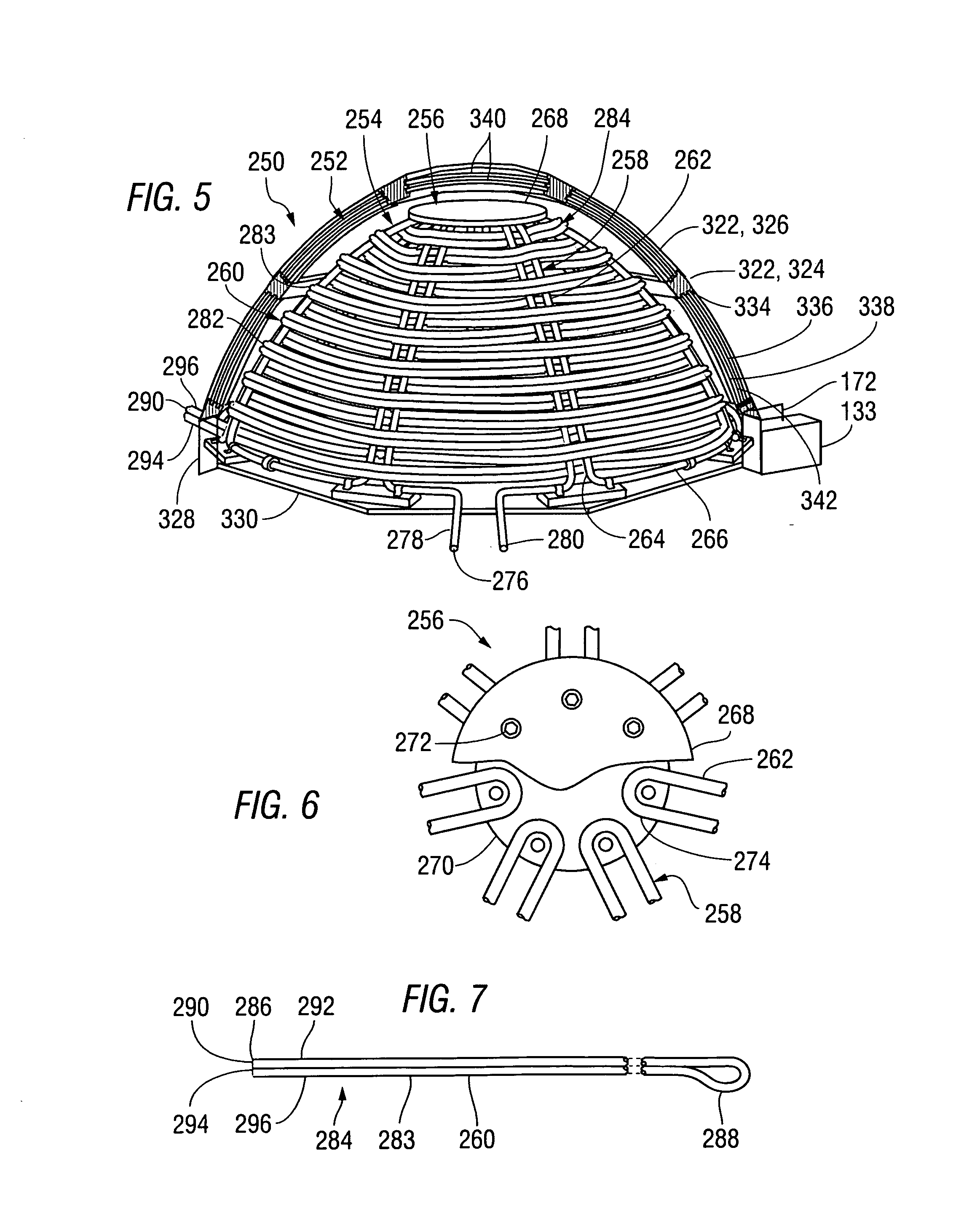
[0069]FIG. 5 is a perspective view of a thermal insulation system 250 including a dome-shaped structure 252 built in accordance with a second version of the invention to extend around and over a dome-shaped solar heat collector 254 built as described in detail in U.S. patent application Ser. No. 12 / 009,092, the disclosure of which has been incorporated herein by reference. A front portion of the dome-shaped structure 252 has been cut away to show the structure of the solar heat collector 254, which includes a frame 256, having a plurality of frame elements 258, and a plurality of transverse elements 260. Each of the frame elements 258 includes a pair of rigid tubular elements 262, extending parallel to one another. The lower ends 264 of rigid tubular elements 262 within adjacent frame elements 258 are connected to one another by peripheral tubular elements 266 within the frame 256.

[0070]FIG. 6 is a fragmentary plan view of the frame 256, showing a central portion thereof, including ...

second embodiment

[0092]FIG. 27 is a cross-sectional end elevation of a thermally insulating panel 610 built for use within a thermally insulating structure built in accordance with the invention, which to include a plurality of such insulating panels 610 attached to a vacuum sustaining unit 133, as described above in reference to FIG. 4.

[0093]The insulating panel 610 includes a pair of side panels 612 held in a spaced-apart condition within a frame 614. An evacuation tube 616 extends through the frame to provide for the evacuation of air from the interior space 618 between the side panels 612, and seals 620 prevent, or at least minimize, the return of air into the interior space 618 following evacuation. In the example of FIG. 27, the side panels 612 are composed of an opaque material, such as a metal, plastic, or composite material including wood chips. Spacers 622 may be attached to extend between the side panels 612, preventing deflection and possible breakage of the side panels 612 due to atmosp...


PUM


Abstract

A thermal insulation system includes an evacuated structure including an internal space in which a vacuum is sustained by a vacuum pump operating when it is determined that a pressure within the internal space has risen to a predetermined level. In one embodiment, such a system is used within a dome structure extending over and around a heat receiving structure within a solar heating system.

Description

RELATED APPLICATIONS[0001]Not ApplicableFEDERALLY SPONSORED RESEARCH OR DEVELOPMENT[0002]Not ApplicableBACKGROUND OF THE INVENTION[0003]1. Field of the Invention[0004]This invention relates to thermal insulation systems, more particularly to such systems including evacuated structures, and yet more particularly to the use of such systems to allow heat retention within solar heat collectors.[0005]double glazed vacuum structures, and, more particularly, to such structures having a means for providing and maintaining a vacuum between spaced-apart glass sheets for thermally insulating solar heat collectors.[0006]2. Summary of the Background Information[0007]A solar heat collector typically includes a heat receiving structure through which a fluid, such as water, is circulated to be heated by solar radiation. The heat receiving structure comprises elements such as piping, tubing, a reservoir tank, and a thermally conductive structure to absorb heat from radiant energy and to transmit the...

Claims


Application Information

Patent Timeline
IPC IPC(8): F24J2/51B65D81/38
CPCE04B1/803F24J2/0015F24J2/04F24J2/08F24J2/24Y02E10/44F24J2/51F24J2002/502F24J2002/503Y02B10/22Y02B80/12F24J2/507F24S10/00F24S10/70F24S20/25F24S23/30F24S80/54F24S80/56F24S80/58F24S80/60F24S2080/502F24S2080/503Y02A30/242Y02B10/20Y02B80/10Y02E10/40
Inventor FLAHERTY, B. MICHAEL
Owner FLAHERTY B MICHAEL
Why Eureka
Try Eureka