
Transmission apparatus comprising at least one positive shifting element hydraulically actuated by way of a hydraulic system

a technology of hydraulic system and transmission apparatus, applied in the direction of fluid actuating clutch, mechanical apparatus, clutch, etc., can solve the problems of disadvantageous displacement of hydraulic actuating piston, inability to initiate control intervention, disadvantageous only being carried out, etc., to achieve simple and cost-effective

Inactive Publication Date: 2009-10-08
ZF FRIEDRICHSHAFEN AG
View PDF15 Cites 20 Cited by
  • Summary
  • Abstract
  • Description
  • Claims
  • Application Information

AI Technical Summary

Benefits of technology

[0012]It is therefore the object of the present invention to provide a transmission apparatus comprising at least one positive shifting element that can be hydraulically actuated by way of a hydraulic system, whereas during the actuation of a positive shifting element the pressure fluctuations in the hydraulic system are at least damped in a simple and cost-effective manner as a function of the operating state.
[0014]As a result, the pressure fluctuations occurring in the hydraulic system in the region of the damping device during actuation of a positive shifting element due to a strongly varying force and distance course are damped, and feedback of massive pressure peaks in the direction of the hydraulic system actuating the shifting element is easily and cost-effectively avoided.
[0019]In an advantageous refinement of the transmission apparatus according to the invention, the damping device comprises a simply acting piston-cylinder unit, whereas the damping element of the damping device is configured as a piston that is axially displaceable in a cylinder which preferably is disposed coaxially to the actuating piston of the shifting element. The damping device configured as a piston-cylinder unit constitutes a simple embodiment which is cost-effective to produce and which can be arbitrarily integrated in the transmission apparatus.
[0021]In an advantageous refinement of the transmission apparatus according to the invention, the actuating piston of the positive shifting element is associated with a distance measuring system by means of which at least one final position of the actuating piston of the shifting element in which the shifting element is engaged can be verified. In this way, the possibility exists to continuously reduce the hydraulic fluid volume flow fed to the positive shifting element, or the piston chamber thereof, in a simple manner just prior to when the final position of the actuating piston is reached, using a pilot valve or the like, in order to avoid pressure fluctuations in the hydraulic system.
[0024]In order to prevent, during a pressure drop in the hydraulic system below the actuating pressure of the positive shifting element, an undesirable return of the actuating piston into the starting position, the form-locking shifting element is basically in a disengaged operating state, a return stroke valve device is placed upstream of the valve device, by means of which it is ensured that the piston chamber of the positive shifting element is not vented in the direction of the region of the hydraulic pressure that controls the system pressure.

Problems solved by technology

In the case of hydraulically actuatable positive shifting elements, the displacement of a hydraulic actuating piston disadvantageously takes place with a strongly varying force-distance curve.
This results from the fact that during actuation of a positive shifting element, such events depend on the position of the two clutch halves of a positive shifting element relative to one another, and cannot be predicted using known distance measuring systems associated with a positive shifting element, such that corresponding control intervention cannot be initiated in a timely manner.
Raising the hydraulic volume flow, however, can disadvantageously only be carried out with delay by way of a corresponding actuation of different valve devices of the hydraulic system.

Method used


Image

  • Transmission apparatus comprising at least one positive shifting element  hydraulically actuated by way of a hydraulic system
  • Transmission apparatus comprising at least one positive shifting element  hydraulically actuated by way of a hydraulic system
  • Transmission apparatus comprising at least one positive shifting element  hydraulically actuated by way of a hydraulic system

Examples


first embodiment

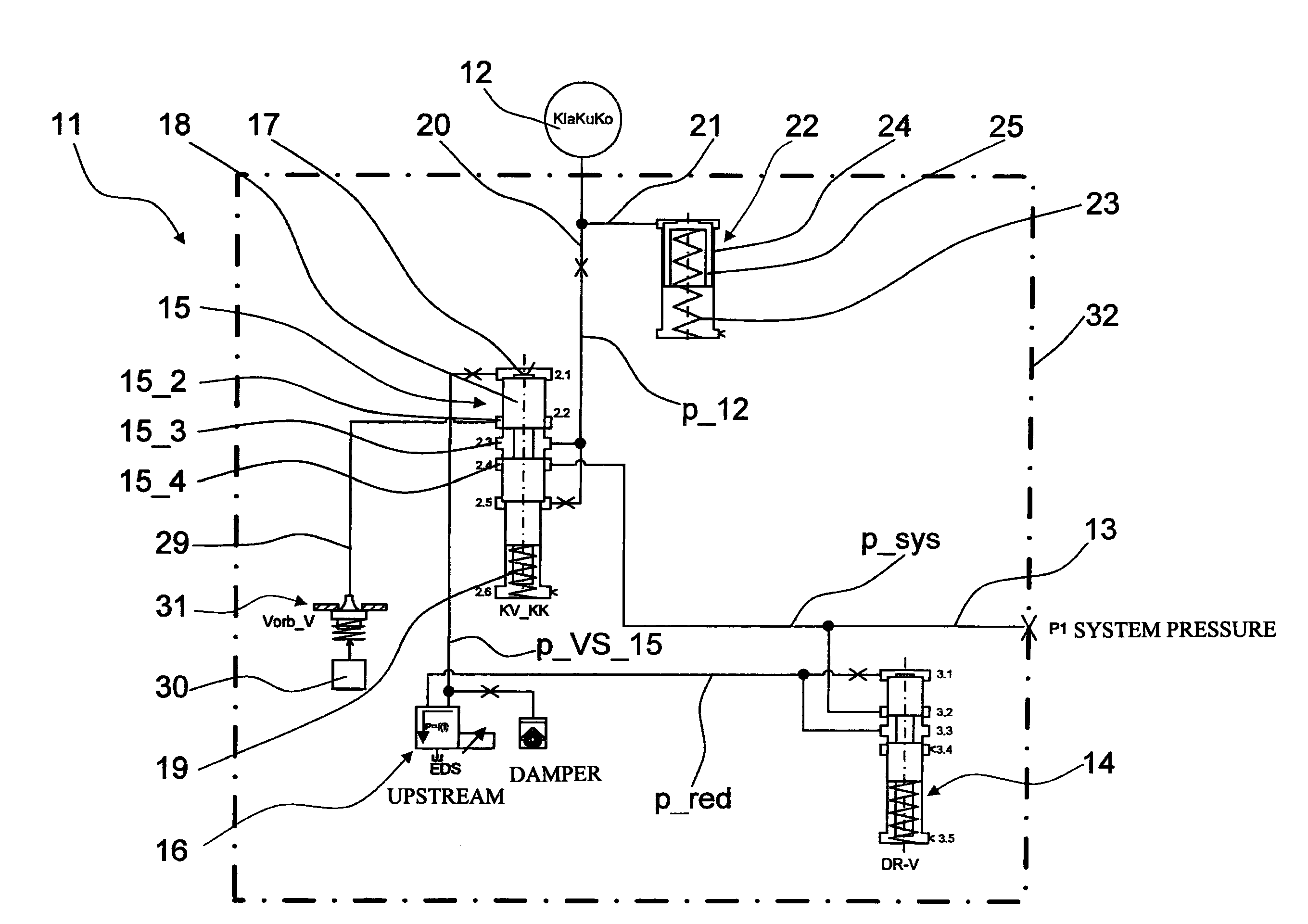
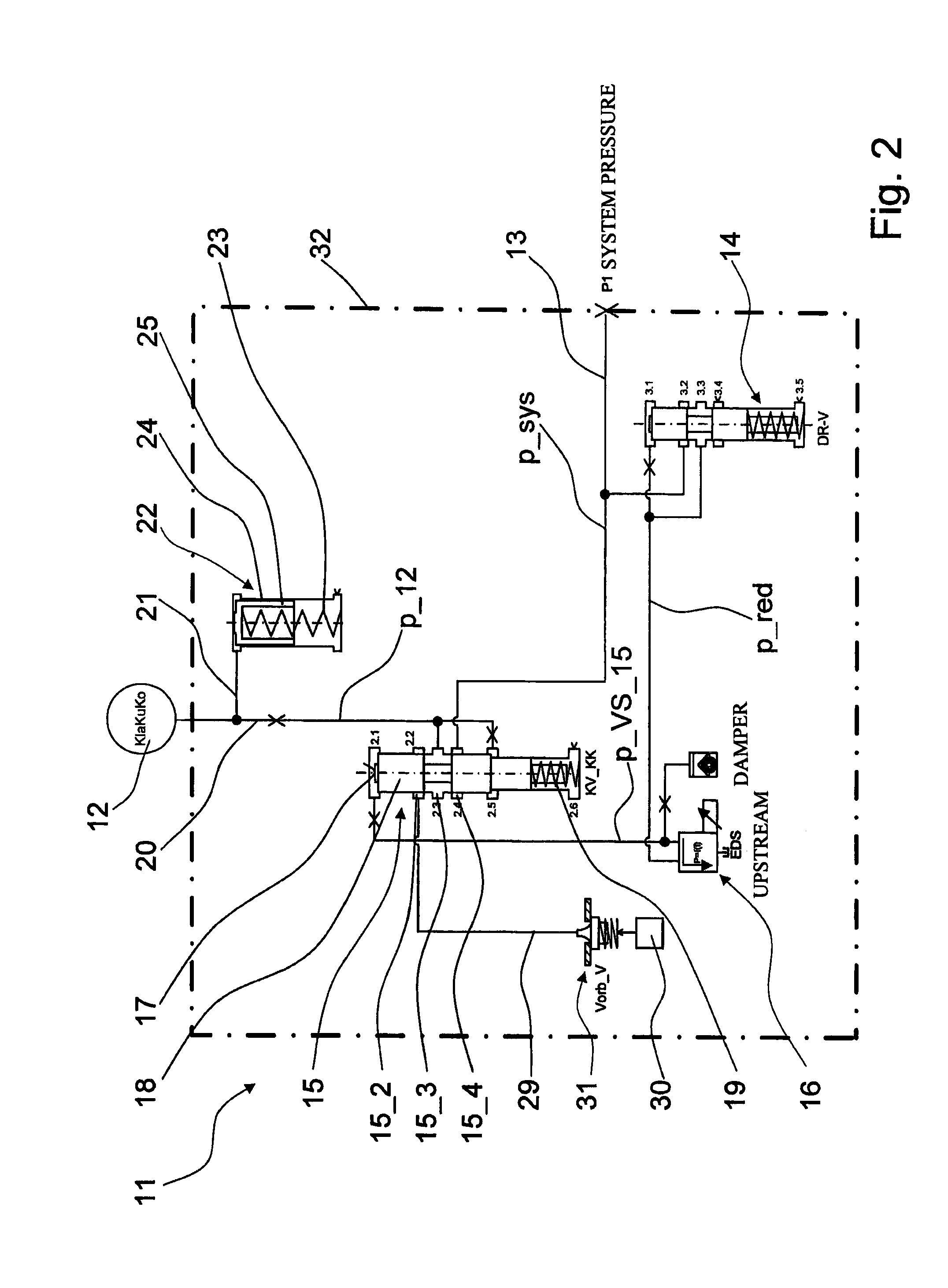
[0040]FIGS. 2 to 5 each show a hydraulic diagram of part of a hydraulic system 11 of the transmission apparatus 10, by way of which a form-lock shifting element 12 of the transmission apparatus 10 can be hydraulically actuated. The different embodiments of the hydraulic system 11 of the transmission apparatus 10 only differ from each other in partial regions, which is why in the description of the embodiments according to FIG. 3 to FIG. 5 basically only the differences from the hydraulic system 11 shown in FIG. 2 are referenced.

[0041]In the first embodiment of the hydraulic system 11 shown in FIG. 2, a system pressure p_sys present in the hydraulic system 11 which is regulated in the region of a system pressure valve that is not shown in detail is applied via a first hydraulic line 13. The system pressure p_sys is forwarded both in the direction of a so-called reducing valve 14 and in the direction of a valve device 15. In the region of the reducing valve 14, the system pressure p_s...

second embodiment

[0046]In the hydraulic system 11 shown in FIG. 3, the valve device 15 is configured as a directly controlled actuating valve on which an axial position of the valve gate 18 is set by way of an electromagnetic actuator or a proportional magnet 26.

[0047]In addition, a return stroke valve device 27 having a bypass throttle 28 is provided upstream of the valve device 15 or upstream of the fourth control guide 15_4 of the valve device 15. A flow direction of a hydraulic fluid volume flow that is conducted via the first hydraulic line 13 is released in the direction of the valve device 15 and hence of the positive shifting element 12 by means of the return stroke valve device 27, while a backflow starting from the fourth control guide 15_4 of the valve device 15 is blocked by the return stroke valve device 27. In this way, a sudden decline in pressure in the region of the positive shifting element 12 as a result of a pressure drop of the system pressure p_sys is easily and cost-effectivel...

fourth embodiment

[0051]the hydraulic system 11 shown in FIG. 4 is provided with an electro-hydraulic actuator 16 configured as a solenoid valve, in order to be able to set the pilot pressure p_VS_15 of the valve device 15 as a function of the operating state. In the region of the solenoid valve 16, the reducing pressure p_red is accordingly converted as a function of the present actuating current and subsequently forwarded in the direction of the control surface 17 of the valve device 15.

[0052]The damping device 22 is disposed outside a hydraulic controller 32 of the hydraulic system 11, whereas between the valve device 15 and the damping device 22 a feed throttle 33A is provided by which the piston 25 of the damping device 22 is disengaged from the valve device 15 controlling the shifting element 12.

[0053]The fourth embodiment of the hydraulic system 11 shown in FIG. 5 substantially corresponds to the first embodiment illustrated in FIG. 2, whereas the damping device 22 contrary to the first embodi...


PUM


Abstract

A transmission apparatus (10) having at least one form-lock shifting element (12) that can be actuated by a hydraulic system (11) which, in the region of a piston chamber, can be subjected to hydraulic pressure (p—12) via a hydraulic fluid-conducting feed line (20) and which can be actuated from a disengaged to an engaged operating state. The hydraulic fluid-conducting feed line (20) of the shifting element (12) is effectively connected to a damping device (22) by which pressure fluctuations, of the hydraulic pressure (p—12) in the feed line (20), can be at least partially compensated.

Description

[0001]This application claims priority from German patent application serial no. 10 2008 001 040.5 filed Apr. 8, 2008.FIELD OF THE INVENTION[0002]The invention relates to a transmission apparatus, comprising at least one positive shifting element that can be hydraulically actuated by way of a hydraulic system.BACKGROUND OF THE INVENTION[0003]Transmission apparatuses or automatic transmissions known from practical applications are typically configured with wet friction shifting elements, such as multi-disk clutches or brakes. The transfer capability of such friction shifting elements is applied, for example, by way of an actuating piston to which hydraulic pressure can be applied, with the actuating piston, as a function of the respectively present hydraulic pressure, pressing together a disk pack comprising inner and outer disks of a shifting element with a force that depends on the pressure that is present. The torque to be conducted via a shifting element is ideally proportional t...

Claims


Application Information

Patent Timeline
IPC IPC(8): F16D25/063
CPCF16H57/0006F16H61/30F16H61/0276
Inventor POPP, CHRISTIANSCHMIDT, THILOSTEINHAUSER, KLAUSARNOLD, JORGHERBETH, VALENTINE
Owner ZF FRIEDRICHSHAFEN AG
Learn More