
Autothermal and mobile torrefaction devices

a torrefaction device and mobile technology, applied in the direction of horizontal chamber coke ovens, lighting and heating apparatus, separation processes, etc., can solve the problems of energy densification, more mass than energy lost to the gas phase, loss of mass and chemical energy into the gas phase, etc., to increase the cost effectiveness, reduce the cost of shipping feedstocks, and reduce the effect of cost per btu

Active Publication Date: 2009-10-08
NORTH CAROLINA STATE UNIV
View PDF13 Cites 70 Cited by
  • Summary
  • Abstract
  • Description
  • Claims
  • Application Information

AI Technical Summary

Benefits of technology

[0012]Additionally, the present invention provides methods for increasing the cost effectiveness of using torrefied biomass as a fuel. Embodiments of the present invention include providing at least one autothermal torrefaction device at a point of operation, such as a point of harvest, which may include but is not limited to, farms and forests in a location remote from a power plant, charging biomass located at the point of operation into the autothermal torrefaction device, and converting the biomass located at the point of operation into torrefied biomass. As such, the costs, per BTU, of shipping the feedstocks are greatly reduced, since the cost of transporting water in the untreated biomass is substantially eliminated and the fuel in now more energy dense.

Problems solved by technology

During the torrefaction of biomass, the biomass partially decomposes and gives off various gases and water vapor, which results in a loss of mass and chemical energy into the gas phase.
However, it is well recognized that more mass than energy is lost to the gas phase during torrefaction.
This phenomenon results in energy densification.
However, traditional approaches lack the efficiency to provide a cost effective means for torrefaction of biomass.
This inefficiency has hindered the potential commercial applications of the torrefaction of biomass.
As such, traditional torrefaction devices are not largely self-sufficient in terms of heat energy used for torrefaction.
Another challenge faced by would-be harvesters and sellers of cellulosic biomass, like wood chips, is its low physical and energy density and low value, which makes it economically disadvantageous to ship it more than 30 to 50 miles to a user.

Method used


Image

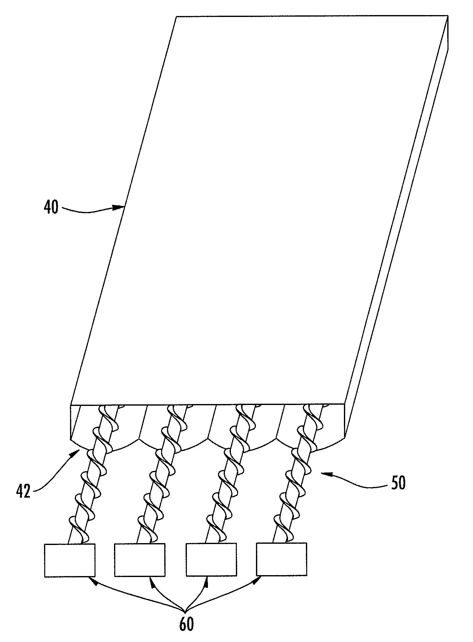
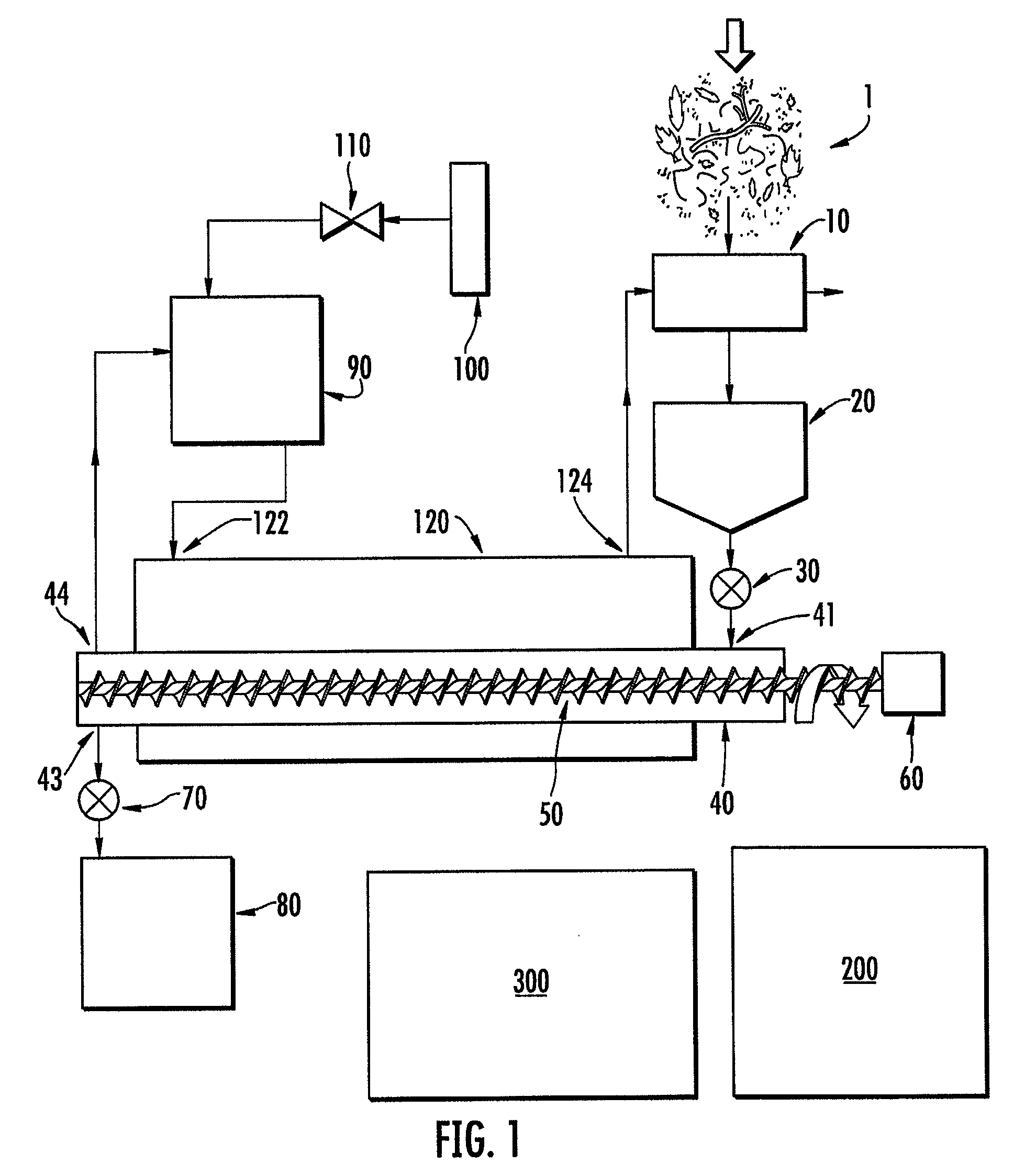
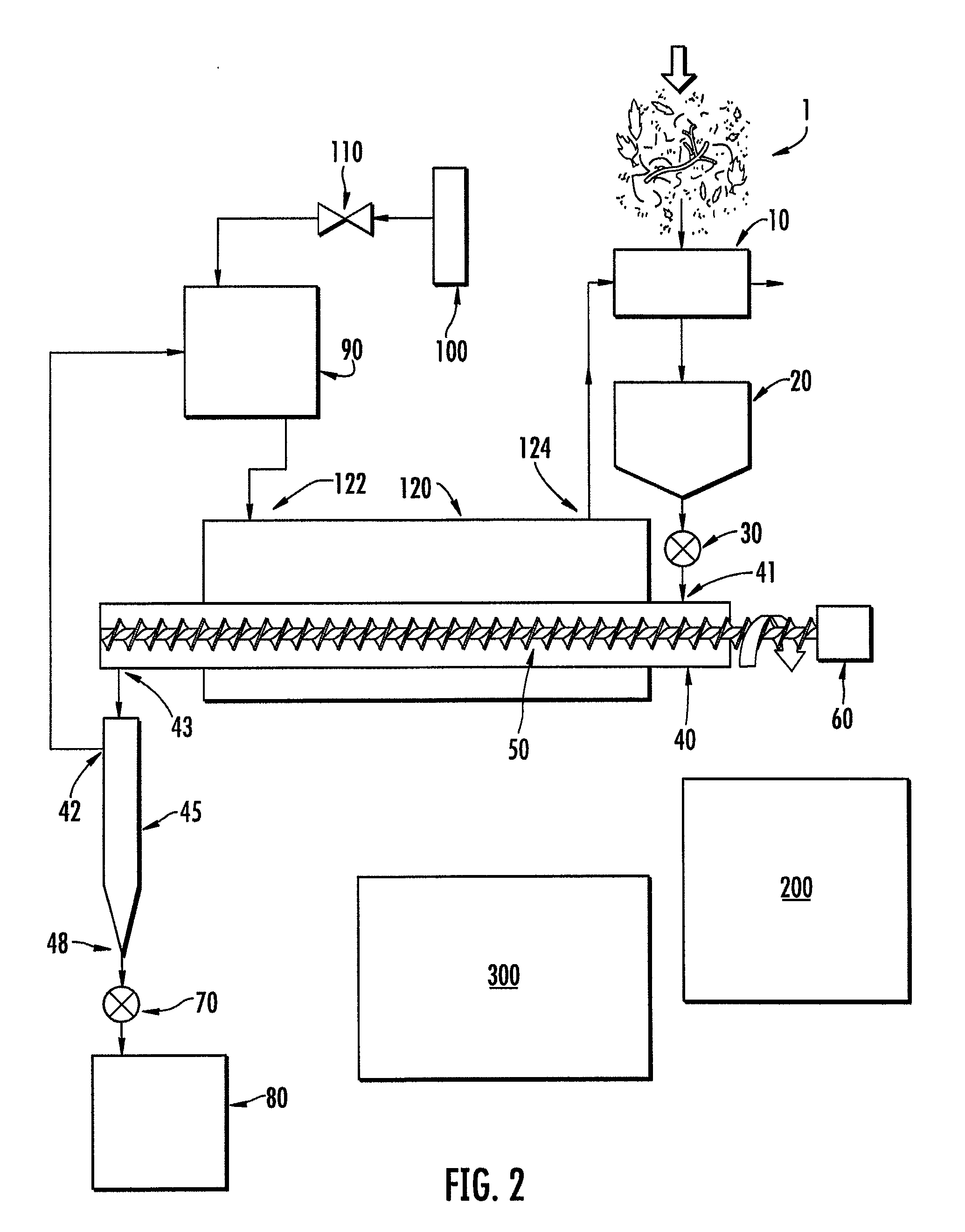
  • Autothermal and mobile torrefaction devices
  • Autothermal and mobile torrefaction devices
  • Autothermal and mobile torrefaction devices

Examples


example

[0060]An autothermal torrefaction device according to one embodiment of the present invention was utilized for the torrefaction of pine logging residues (small diameter wood, bark, needles). The torrefaction device included 6 torrefaction chambers each having an overall length of 20 feet. The exterior housing or outer jacket surrounding the torrefaction chambers comprised a box having an internal width of 5 feet, an internal height of 5 feet and an internal length of 14 feet. As such, 14 feet of the 20 foot torrefaction chambers were surrounded by the outer jacket.

[0061]The biomass (i.e., the pine logging residues) was fed through a ½″ screen on a hammermill. The water content varied from particle to particle but the overall average water content was approximately 50% by weight. The ground biomass was conveyed in a trough to a feed hopper. While being conveyed in the trough to the feed hopper, hot exhaust gases were blown across the biomass in the trough as well as around the outsid...


PUM


Abstract

The present invention provides an autothermal torrefaction device, which can be either stationary of mobile. Embodiments of the present invention include a torrefaction chamber having a chamber inlet for receiving biomass and at least one chamber outlet. The torrefaction chamber can be substantially surrounded by an exterior housing defining an outer jacket and having a jacket inlet and a jacket outlet. The outer jacket and torrefaction chamber define a space therebetween such that a burner unit including an inlet operatively connected to the chamber outlet and an outlet operatively connected to the jacket inlet allows vapors produced or released from within the torrefaction chamber to travel into the burner unit for combustion of at least a portion of the vapors and subsequently travel through the space between the jacket and the torrefaction chamber to provide heat necessary for autothermal torrefaction of biomass.

Description

CROSS-REFERENCE TO RELATED APPLICATIONS[0001]This application claims the benefit of U.S. Provisional Application No. 61 / 042,034, filed Apr. 3, 2008, which is incorporated by reference in its entirety.BACKGROUND OF THE INVENTION[0002]1. Field of the Invention[0003]The present invention relates generally to an autothermal torrefaction device that is largely self-heated, mobile or stationary, and a process for the torrefaction of biomass.[0004]2. Description of Related Art[0005]Torrefaction is considered to be a pre-treatment technology to make biomass more suitable for co-firing with coal applications. Torrefaction is a thermal process operated between 200° C. and 300° C. in the absence of oxygen and characterized by residence times typically around 1 hour or greater. Torrefaction processes are usually carried out at near atmospheric pressures. Torrefied biomass exhibits increased brittleness, improved grindability which may enable increased co-firing rates in the future.[0006]During ...

Claims


Application Information

Patent Timeline
IPC IPC(8): C10B21/20C10B51/00C10B53/02C10L5/08
CPCC10B47/44C10B53/02C10L5/363C10L5/44C10L9/08Y02E50/30F26B17/20F26B23/022Y02E50/10Y02E50/14Y02E50/15C10L9/083
Inventor HOPKINS, CHRISTOPHER B.BURNETTE, JR., RUCKER PRESTON
Owner NORTH CAROLINA STATE UNIV
Learn More