
Distance measuring device and distance measuring method

Inactive Publication Date: 2009-10-08
SAIKA TECH INST FOUND
View PDF11 Cites 14 Cited by
  • Summary
  • Abstract
  • Description
  • Claims
  • Application Information

AI Technical Summary

Benefits of technology

[0039]The distance measuring device and distance measuring method according to the claimed invention formed as above detect a mixed wave of a progressive wave and a reflected wave reflected by a measurement object; there is no need to prevent the progressive wave from leaking into a receiving antenna, a simple construction can be achieved, and a distance measuring device of low cost and a small size can be obtained.
[0040]In addition, by finding a distance spectrum from a mixed wave of a progressive wave having a plurality of different frequency components and its reflected wave, the distance between the measurement object and the mixed wave detection unit can be found from the distance whose spectrum becomes the peak of the size.
[0041]When the distance to the measurement object is measured by the use of a standing wave, it is, in principle, unable to make the frequency change-over time shorter than the time required for forming a standing wave from when the progressive wave frequency is changed over, and the measurement is therefore subject to the influence of the Doppler effect and a measurement error is generated, but in the claimed invention, there is, in principle, no concept of changing over the frequency, the observation time is able to be shortened to such a level that the influence of the Doppler effect can be virtually ignored, and the correct distance is able to be measured irrespective of the travel speed and travel direction of the measurement object.
[0042]In addition, even when the distances of a plurality of measurement objects come closer and the speed differences are large, which are difficult to measure by a distance measuring device using a standing wave, the position of each measurement object can be correctly measured.
[0043]In addition, a plurality of mixed wave detection units are installed to different positions, respectively and the distance spectrum is found from a plurality of mixed waves detected by a plurality of mixed wave detection unit; therefore, distance measurement with still higher reliability and higher accuracy can be conducted.
[0044]In addition, when a double-modulated signal is outputted from a signal source, there is no need to use a high-cost microprocessor, etc. which can carry out spectrum analyses at high speed, and a signal processor is configured by an envelop detector, square-law detector, synchronous detector, quadrature detector, band pass filter, matched filter, and other devices, and detects the size of distance spectrum (signal level), and therefore, a signal processor of a processing speed nearly same as that of the signal processor using a microprocessor, etc. can be obtained at low cost. That is, a distance measuring device at low cost and fast signal processing speed can be obtained.

Problems solved by technology

At the same time, the foregoing radars basically measure round-trip time of signals to a measurement object, and resolution within several tens of meters lacks; therefore, it is difficult to measure the close range within several tens of meters.
Furthermore, because the FMCW radar measures distance to the measurement object from the frequency difference between transmitted signals and reflected signals, it has problems of a need of the linearity of frequency change of transmitted signals as well as of a “False Object” which is caused by transmitted signals that leak to the receiving side; it also need accurately output transmitted signals so as to satisfy the linearity of frequency changes, separate antennas on the transmitting and receiving sides so that transmitted signals do not leak into the receiving side to prevent an occurrence of “False Object”, and others, and it has been difficult to achieve a simple construction.
The distance measuring device set forth in patent document 1, however, is effective when travel speed between the measurement object and the travel distance measuring device is comparatively slow and the travel distance within the measurement time can be ignored but when the travel speed between the measurement object and the distance measuring device is fast and the travel distance within the measurement time is unable to be ignored, the distance measuring device is difficult to obtain correct measured value due to the Doppler effect.

Method used


Image

  • Distance measuring device and distance measuring method
  • Distance measuring device and distance measuring method
  • Distance measuring device and distance measuring method

Examples


first embodiment

[0116]A technical outline of the first embodiment of the distance measuring device and the distance measuring method related to the claimed invention will be described as follows.

[0117](Technical Outline 1)

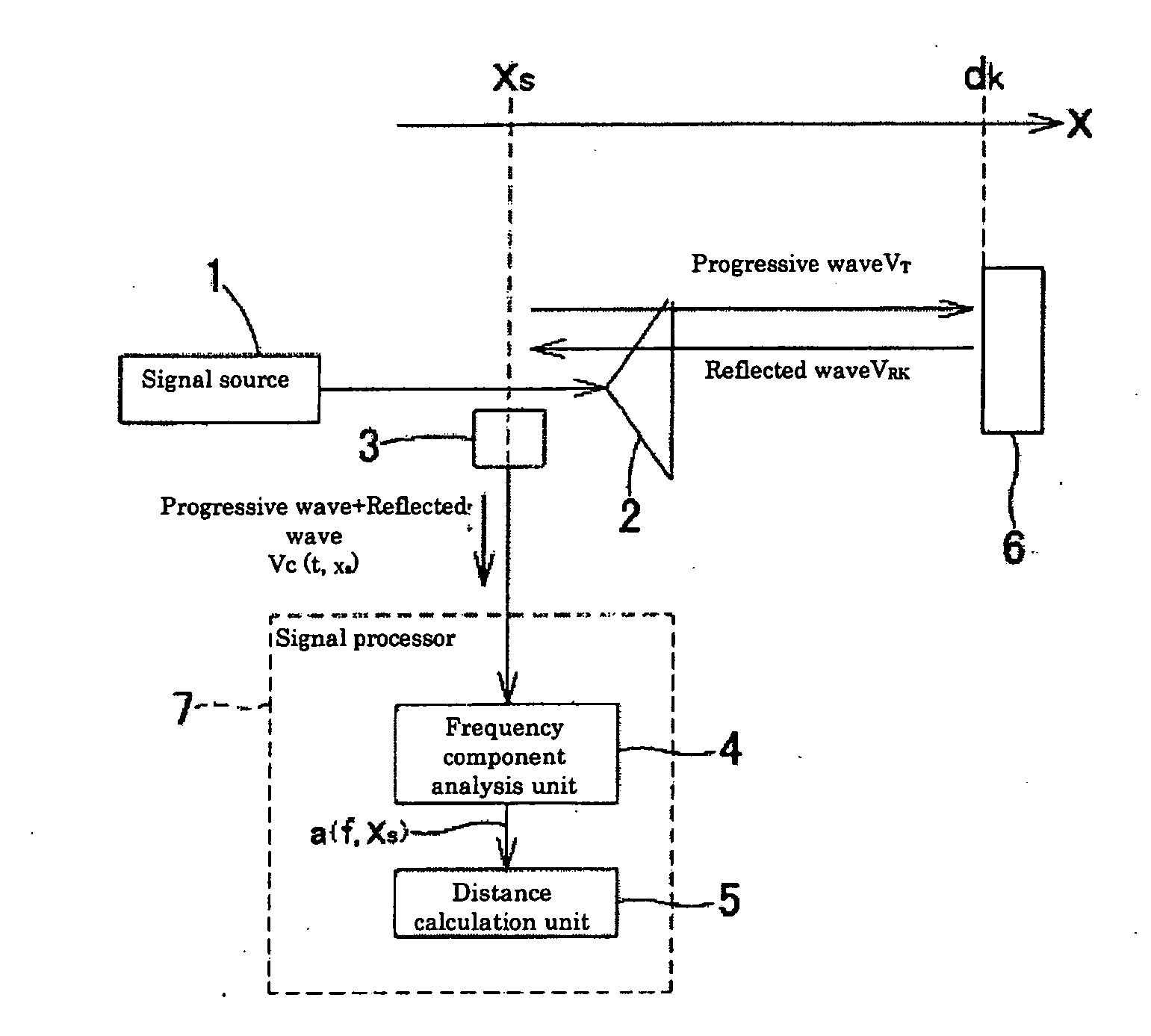
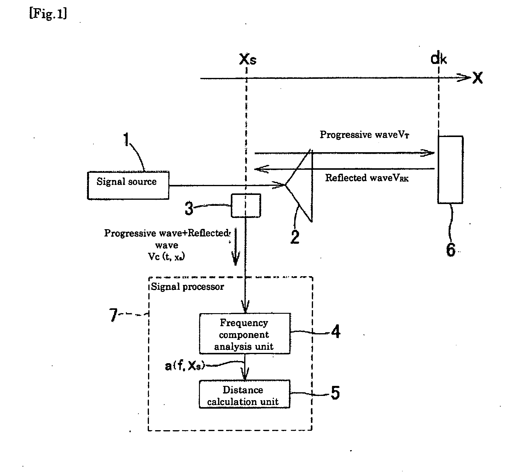
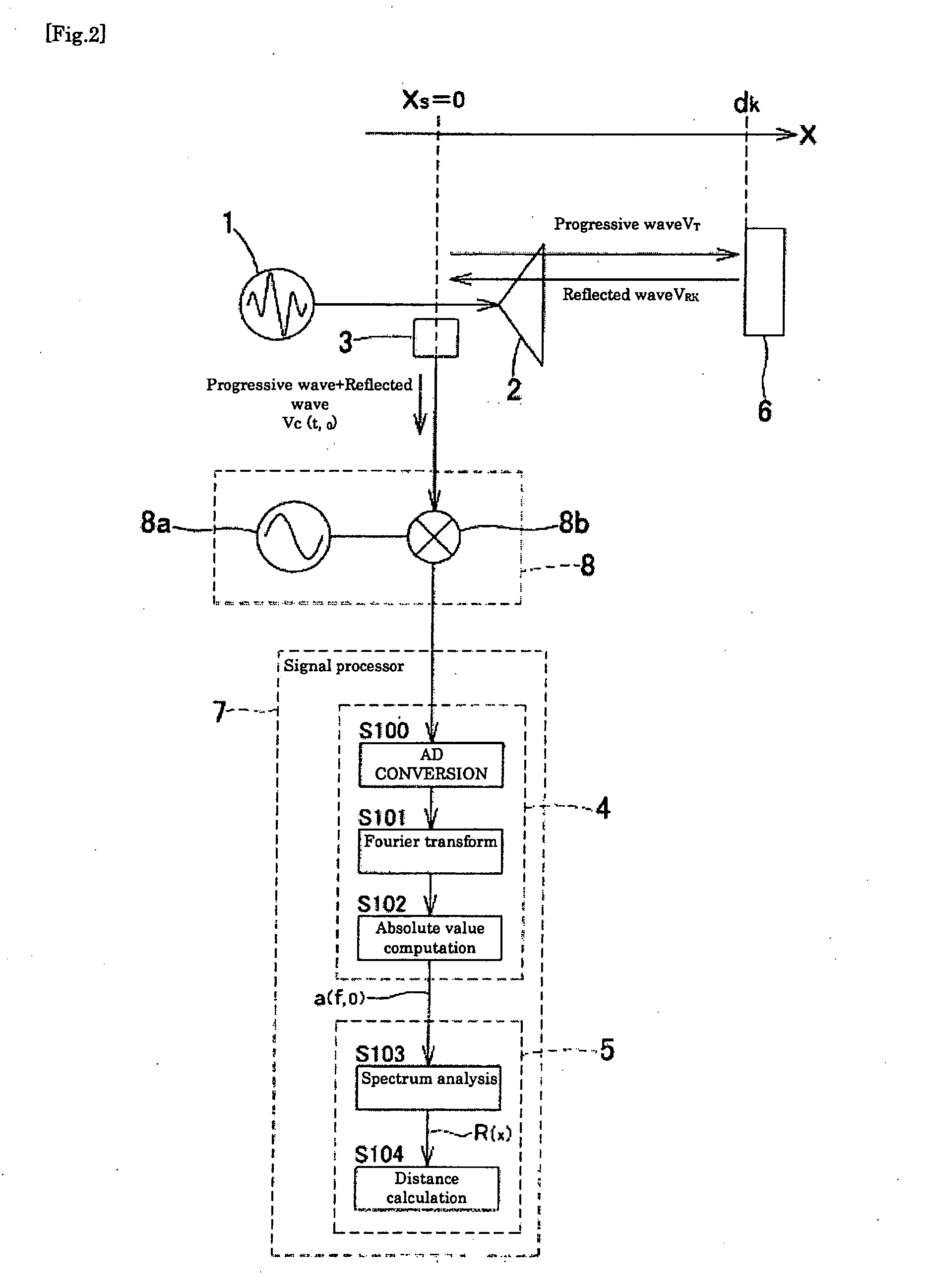
[0118]FIG. 1 is an illustration that explains the outline of a distance measuring device related to the claimed invention. The distance measuring device related to the claimed invention transmits a signal (progressive wave VT) outputted from a signal source 1 as an undulation from a transmission unit 2 to a measurement object 6, detects a mixed wave VC of a reflected wave VRk reflected by the kth measurement object 6 and the progressive wave VT at a mixed wave detection unit 3, analyzes a frequency component (a(f, xs)) of the mixed wave at a frequency component analysis unit 4, calculates a distance spectrum R(x) at a distance calculation unit 5, and measures the distance to the measurement object 6.

[0119]The signal source 1 outputs a signal having a plurality of different frequen...

second embodiment

[0165]A technical outline of the second embodiment of the distance measuring device and the distance measuring method related to the claimed invention will be described as follows.

[0166](Technical Outline 2)

[0167]FIG. 8 is an illustration that explains the outline of a distance measuring device related to the claimed invention. The distance measuring device related to the claimed invention transmits a signal outputted from a signal source 9 as an undulation from a transmission unit 2 to a measurement object 6, detects a mixed wave VC of a reflected wave VRk reflected by the kth measurement object 6 and the progressive wave VT at a mixed wave detection unit 3, detects an amplitude component (a(t, xs) of the mixed wave at an amplitude component detection unit 10, calculates a distance spectrum R(x) at a distance calculation unit 11, and measures the distance to the measurement object 6.

[0168]The signal source 9 outputs a frequency-modulated signal obtained by frequency-modulating a ca...

third embodiment

[0209]A technical outline of the third embodiment of the distance measuring device and the distance measuring method related to the claimed invention will be described as follows.

[0210](Technical Outline 3)

[0211]FIG. 15 is an illustration that explains the outline of a distance measuring device related to the claimed invention. The distance measuring device related to the claimed invention transmits a signal outputted from a signal source 13 as an undulation from a transmission unit 2 to a measurement object 6, detects a mixed wave VC of a reflected wave VRk reflected by the kth measurement object 6 and a progressive wave VT at a mixed wave detection unit 3, processes this mixed wave VC with a signal processor 14, and finds the distance to the measurement object 6. The signal processor 14 comprises an amplitude component detection unit 15, single frequency selection unit 16, signal level detection unit 17, and distance calculation unit 18, and an amplitude component (a(t, xs)) of th...


PUM


Abstract

There are provided a distance measuring device and a distance measuring method characterized by “simple configuration”, “capability of measuring a near distance”, and “a small measurement error” like a distance measuring device using a standing wave. The distance measuring device includes a signal source (1) for outputting a signal having a plurality of different frequency components within a particular bandwidth, a transmission unit (2) for transmitting a signal as an undulation, s mixed wave detection unit (3) for detecting a mixed wave VC obtained by mixing a progressive wave VT transmitted and a reflected wave VRk of the progressive wave VT reflected by a measurement object (6), a frequency component analysis unit (4) for analyzing the frequency component of the mixed wave VC detected, and a distance calculation unit (5) for obtaining a distance spectrum by subjecting the analyzed data further to spectrum analysis, thereby calculating the distance to the measurement object (6).

Description

TECHNICAL FIELD[0001]The present invention relates to a distance measuring device and distance measuring method, and more particularly, to a distance measuring device and distance measuring method which detects mixed wave of a progressive wave outputted from a signal source and a reflected wave of the progressive wave reflected by a measurement object, and measures distance to the measurement object.BACKGROUND ART[0002]Conventionally, as a distance measuring device by the use of electric wave, a pulse radar, an FMCW radar, and other radars are known.[0003]The pulse radar transmits a pulse signal, measures the time in which the pulse signal is reflected by a measurement object, and finds the distance to the measurement object. In addition, the FMCW radar transmits a frequency-swept continuous wave and measures distance to a measurement object from the frequency difference between the transmitted signals and reflected signals. In addition to this, there are spread spectrum radar, code...

Claims


Application Information

Patent Timeline
IPC IPC(8): G01S13/32
CPCG01S13/32G01S13/08G01S13/10H03M1/12
Inventor UEBO, TETSUJI
Owner SAIKA TECH INST FOUND
Learn More