
Carbon nanotube transparent electrode and method of manufacturing the same

a technology of carbon nanotubes and transparent electrodes, applied in the direction of transportation and packaging, synthetic resin layered products, coatings, etc., can solve the problems of reducing the stability of the application process of cnt transparent electrodes to devices, reducing the roughness or film uniformity of surfaces, and reducing the conductivity of cnt transparent electrodes. , to achieve the effect of enhancing the conductivity of cnt transparent electrodes, reducing electrical conductivity, and reducing electrical conductivity

Inactive Publication Date: 2009-10-08
SAMSUNG ELECTRONICS CO LTD +1
View PDF7 Cites 20 Cited by
  • Summary
  • Abstract
  • Description
  • Claims
  • Application Information

AI Technical Summary

Benefits of technology

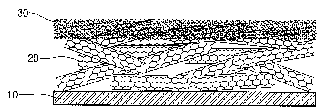
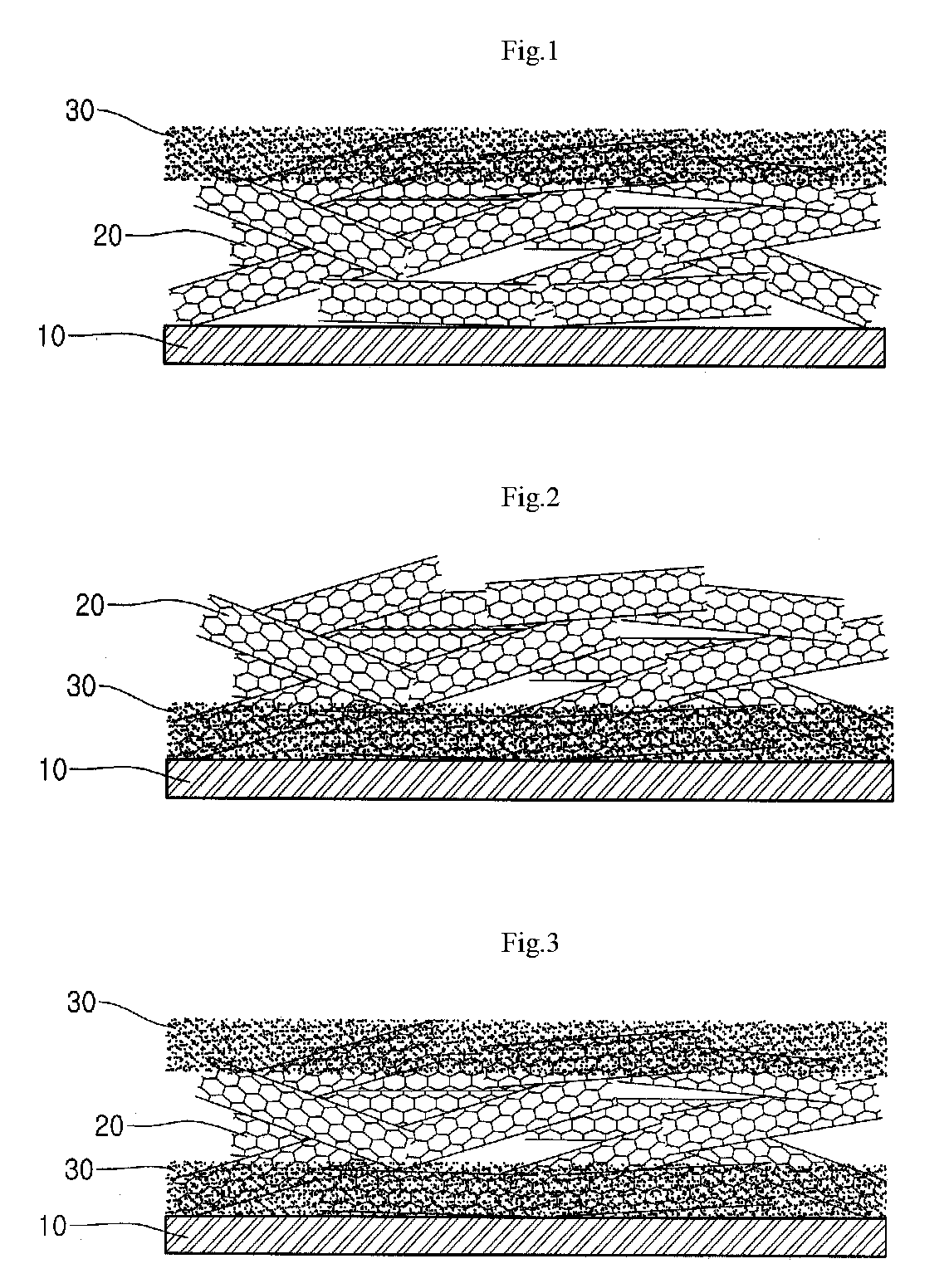
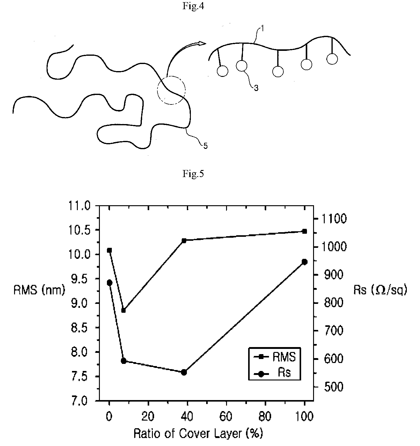
[0008]The inventors disclose an exemplary embodiment of a novel carbon nano-tube (CNT) transparent electrode, which includes a CNT layer and a cover layer for the CNT layer. The CNT layer may consist essentially of CNTs only without other materials such as binders or dispersing agents in order to enhance electrical conductivity. Further, the cover layer may include conductive particles and a polymer. The cover layer may be formed together with the CNT layer in order to prevent problems possibly occurring when using only the CNT layer (without the cover layer) as part of the CNT transparent electrode. The presence of the CNT layer without the cover layer may lead to problems, such as for example, a reduction of surface roughness or of film uniformity. Further, it can lead to a reduction of adhesion between a CNT transparent electrode including the CNT layer without the cover layer and a substrate, which may lead to a reduction in the stability of the process of applying the CNT transparent electrode to devices.
[0011]Since the CNT layer essentially consists of CNTs only and does not contain other materials such as organic materials, which may reduce electrical conductivity, the CNT layer can contribute to enhancing the conductivity of the CNT transparent electrode.
[0012]Meanwhile, since the cover layer covering the CNT layer comprises conductive particles, the cover layer can contribute to enhancing the conductivity of the CNT transparent electrode. Further, since the cover layer covering the CNT layer comprises a polymer, the cover layer can contribute to enhancing roughness or film uniformity as well as adhesion between the CNT transparent electrode and the substrate, which may improve stability in the process of applying the CNT transparent electrode to devices.

Problems solved by technology

The presence of the CNT layer without the cover layer may lead to problems, such as for example, a reduction of surface roughness or of film uniformity.
Further, it can lead to a reduction of adhesion between a CNT transparent electrode including the CNT layer without the cover layer and a substrate, which may lead to a reduction in the stability of the process of applying the CNT transparent electrode to devices.

Method used


Image

  • Carbon nanotube transparent electrode and method of manufacturing the same
  • Carbon nanotube transparent electrode and method of manufacturing the same
  • Carbon nanotube transparent electrode and method of manufacturing the same

Examples


experiment 1

Characteristic Change Depending on Cover-Layer Formation Ratio

[0073]An experiment was carried out measuring characteristic changes depending on the cover-layer formation ratio with respect to the entire layer. Here the electrode type was the upper-cover-type, and PET was used as the substrate.

[0074]The cover-layer formation ratio can be defined as follows. First, the total weight of the entire layer can be represented by Expression 1.

Total weight of CNT in entire layer=weight of CNT layer+weight of CNT present in the cover layer  Expression 1

[0075]For reference, since the CNT layer is composed of CNT only after washing, the weight of the CNT layer is the weight of the CNT in the CNT layer. Since the cover layer is composed of CNT (conductive particle) and polymer, the weight of the cover layer can be calculated by adding the weight of polymer and the weight of CNT.

[0076]The ratio of the cover layer can be represented by Expression 2.

Ratio of Cover Layer (%)=[weight of CNT present in...

experiment 2

Characteristic Change Depending on Electrode Type

[0081]The ratio of cover layer was set to be 37%, which is approximate to the ratio of cover layer of Experiment 1 (38%), and the electrode types on the substrate (PEN) were set to be lower-cover-type and upper-and-lower-cover-type, differently from that of Experiment 1. In the case where the upper-and-lower-cover-type was adopted, 7.4% of 37% was set to correspond to the cover layer covering the upper portion of the electrode. Table 2 shows the experiment results.

TABLE 2SheetRoughnessresistanceTrans-(RMS)(Rs)mittanceLower-cover-type7.489 nm534.77 Ω / sq87.0%electrode [ratio ofcover layer - 37%]Upper-and-lower-5.824 nm525.71 Ω / sq87.4%cover type electrode[ratio of cover layer -37%; upper portion7.4% + lower portion29.6%]

[0082]As shown in Table 2, when the lower-cover-type electrode was used, the roughness decreased to 7.489 nm, and the sheet resistance decreased to 534.77 Ω / sq. And, when the upper-and-lower-cover-type electrode was used,...

experiment 3

Change in Composition of Cover-Layer Forming Solution

[0083]The ratio of cover layer was set to be 31%, the type of the polymer in the cover-layer forming solution was replaced with polystyrene sulfonic acid (PSS) and Nafion®, the electrode type was set to be lower-cover-type, and the substrate was PET substrate. Table 3 shows the experiment results. For reference, Table 3 also shows the case where the ratio of cover layer is 0% and the case where polyacrylic acid (PAA) is used and the ratio of cover layer is 37%.

TABLE 3Ratio of CoverRoughnessSheet resistanceLayer(RMS)(Rs)Transmittance 0%10.700 nm872.4 Ω / sq89.4%37% (PAA used)10.257 nm471.3 Ω / sq88.5%37% (PSS used)10.459 nm478.1 Ω / sq89.1%37% (Nafion ®10.440 nm750.0 Ω / sq89.7%used)

[0084]As shown in Table 3, when PSS was used, the sheet resistance and the roughness were 478.1 Ω / sq and 10.495 nm, respectively. When Nafion® was used, the sheet resistance was 750.0 Ω / sq and the roughness was 10.440 nm. The sheet resistance in the case using ...


PUM

PropertyMeasurementUnit
Fractionaaaaaaaaaa
Fractionaaaaaaaaaa
Weightaaaaaaaaaa

Abstract

A CNT transparent electrode may have a CNT layer consisting essentially of CNT only, together with a cover layer that may include conductive particles and a polymer. The cover layer may cover an upper and / or a lower portion of the CNT layer. The CNT transparent electrode including the CNT layer which essentially consists of CNT only and does not contain other materials such as a binder or a dispersing agent can exhibit excellent conductivity. When the CNT layer is covered by the cover layer, surface roughness, film uniformity, adhesion between the CNT transparent electrode and the substrate and stability in the process of applying the CNT transparent electrode to devices can be enhanced, compared to the case where only the CNT layer is used.

Description

[0001]This application claims priority to Korean Patent Application No. 10-2008-0031403, filed on Apr. 3, 2008, and all the benefits accruing therefrom under U.S.C. § 119, the entire contents of which are hereby incorporated by reference.BACKGROUND[0002]1. Field of the Invention[0003]This disclosure relates to a carbon nano-tube (CNT) transparent electrode and a method of manufacturing the same.[0004]2. Description of the Related Art[0005]CNTs have excellent conductivity as well as strength, and can be bent easily without breaking. Therefore, CNTs can be used to manufacture flexible transparent electrodes.[0006]A flexible transparent electrode using CNTs (hereinafter “CNT transparent electrode”) can be applied to various display devices such as liquid crystalline displays (LCD), organic light emitting diodes (OLED), paper-like display, and the like. Further, the flexible transparent electrode can be applied to energy devices such as solar cells.[0007]For manufacturing a CNT transpar...

Claims


Application Information

Patent Timeline
IPC IPC(8): B32B27/06B05D5/12
CPCY10T428/30H01B1/24Y02E10/50B82B3/00H01L31/04H01J11/22B82Y40/00
Inventor YOON, SEONMICHOI, JAEYOUNGSHIN, HYEON JINPAIK, UNGYUCHA, IN SUNG
Owner SAMSUNG ELECTRONICS CO LTD
Learn More