
Deep brain stimulation implant with microcoil array

a brain stimulation and microcoil technology, applied in the field of deep brain stimulation implants with microcoil arrays, can solve the problems of poor spatial resolution of existing dbs implants, limited number of electrodes per implant, and limited number of conventional cylindrical dbs implants

Active Publication Date: 2009-10-08
THE GENERAL HOSPITAL CORP
View PDF22 Cites 48 Cited by
  • Summary
  • Abstract
  • Description
  • Claims
  • Application Information

AI Technical Summary

Benefits of technology

[0015]In accordance with one aspect of the present invention, a device for stimulating biological tissue, such as when performing deep brain stimulation, includes an insertable elongated implant with a plurality of microcoils. The implant extends along a longitudinal axis and has a proximal portion and a distal portion. A plurality of electrical conductors extend along the longitudinal axis of the implant and are coupled to the plurality of microcoils. An electrically isolating barrier covers the plurality of microcoils. A coupling connects the microcoils to a power source through the plurality of electrical conductors such that the plurality of microcoils can be driven to produce magnetic fields suitable for deep brain stimulation.

Problems solved by technology

One drawback is the poor spatial resolution of existing DBS implants.
Conventional cylindrical DBS implants have a very limited number of electrodes per implant because of spatial requirements between electrodes to prevent electrophoresis.
Because of these gaps between electrodes, electrical stimulation of the brain may not be optimized.
Further, during placement and setup of a DBS implant, a large variability exists between the location and size of the stimulation area within the brain and the amount of current to be delivered.
A second drawback of existing DBS systems is the large size requirement for electrodes in order to limit the effects of high current densities and electrophoresis.
In practice, the dimension of each electrode is roughly equal to the portion of the brain intended to be stimulated, thus limiting the flexibility for spatially selective stimulation of the brain.
A third drawback of existing DBS systems is the use of copper-containing electrical leads between the pulse generator and the electrodes.
These leads are not compatible with magnetic resonance imaging (MRI) procedures and special precautions must be adhered to during MRI procedures.
While copper is not a ferromagnetic material and thus, the electrodes do not move or become dislodged when subjected to strong magnetic fields, large electrical currents may nonetheless be induced resulting in thermal damage to the brain tissue.
DBS implants with elongated configurations or that are electronically activated are particularly prone to having induced currents.
However, these implants still use capacitive coupling to deliver an electric current and thus, do not overcome the problems associated with direct electrode-to-tissue contact.
Although non-invasive, TMS has its own drawbacks.
However, high intensity electric fields (induced by the strong magnetic fields) are known to cause epileptic seizures and other neurological problems.
Further, the induced electric fields are not sufficiently focused and, as a result, generalized stimulation throughout the brain may occur.
Still further, the amount of electric current used to drive such TMS coils is prohibitively large.

Method used


Image

  • Deep brain stimulation implant with microcoil array
  • Deep brain stimulation implant with microcoil array
  • Deep brain stimulation implant with microcoil array

Examples


Embodiment Construction

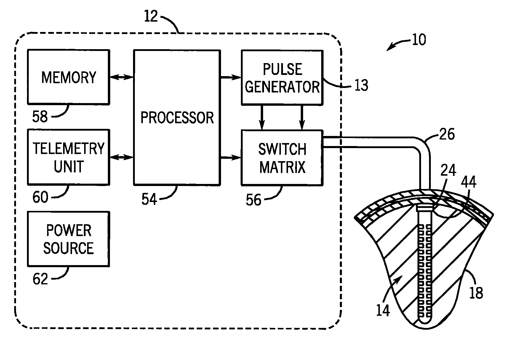
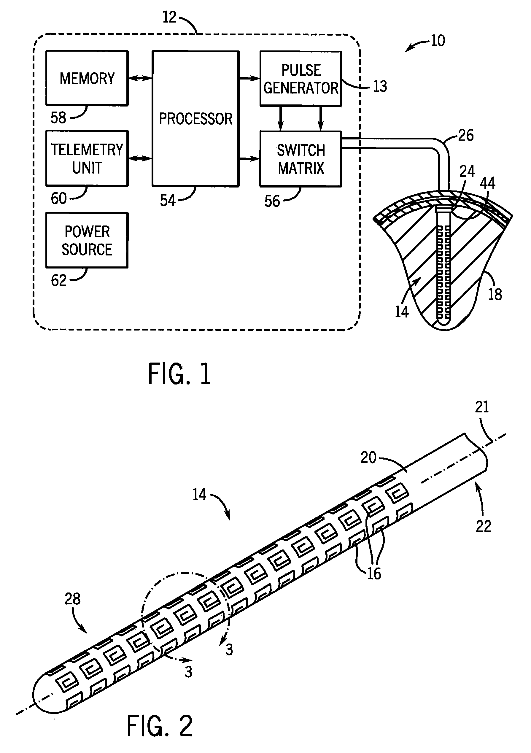
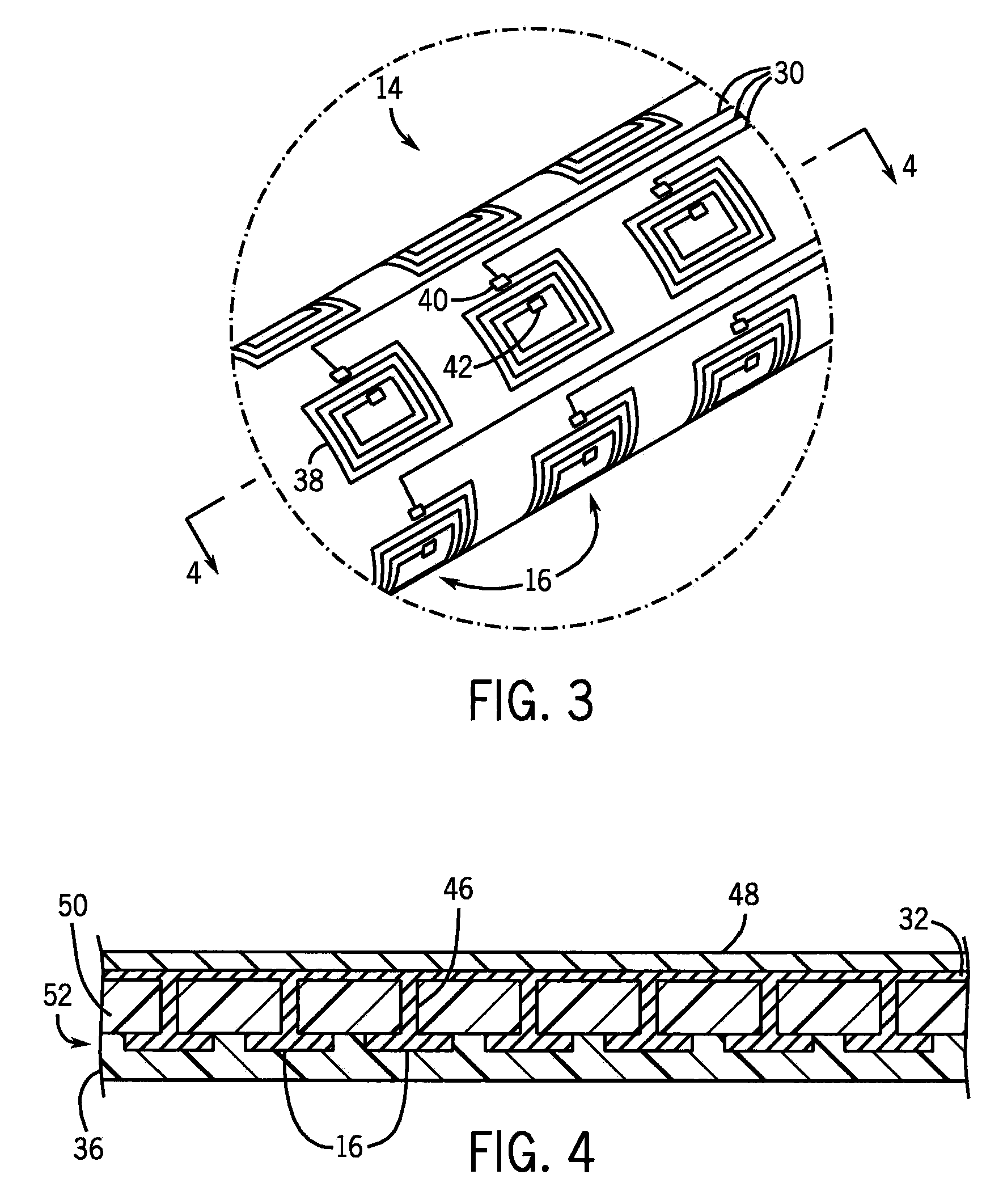
[0023]Referring initially to FIGS. 1 and 2, a deep brain stimulation system 10 includes a stimulator 12 coupled to an implantable device 14 (referred to hereinafter as an ‘implant’) with an array of planar electromagnetic microcoils 16. The stimulator 12 includes a pulse generator 13 that generates electrical pulses for delivery to a targeted stimulation site in a human brain 18 via the implant 14. The electrical pulses cause the microcoils 16 to produce magnetic fields that are directed perpendicularly into the brain 18. The magnetic fields, in turn, induce electrical currents in brain tissue to excite the neurons therein.

[0024]The implant 14 is configured as an elongated insertion probe with a narrow cylindrical shaft 20 defining a longitudinal axis 21. The shaft 20 includes a proximal portion 22 with a connector 24 coupled to the stimulator 12 via a pair of leads 26 and a distal portion 28 with a plurality of spaced-apart microcoils 16. The implant 14 also includes a plurality of...


PUM


Abstract

An implant for deep brain stimulation (DBS) has an array of electromagnetic microcoils dispersed over the length of the implant. The microcoils produce magnetic fields that are directed into, and induce current in, the adjacent brain tissue. The microcoils may be selectively operated to direct and focus electrical stimulation to targeted areas of the brain. The implant is useful in studying or treating neurophysiological conditions associated with the deep regions of the brain such as Parkinson's disease, drug addiction, and depression.

Description

CROSS-REFERENCE TO RELATED APPLICATIONS[0001]This application is based on, fully incorporates herein by reference, and claims the benefit of U.S. Provisional Application Ser. No. 61 / 042,070, filed on Apr. 3, 2008, and entitled “DEEP BRAIN STIMULATION IMPLANT WITH MICRO MAGNETIC STIMULATION ARRAY”.STATEMENT REGARDING FEDERALLY SPONSORED RESEARCH[0002]This invention was made with government support by the National Institute of Health under Grant No.: ______. The United States Government has certain rights in this invention.BACKGROUND OF THE INVENTION[0003]The present invention relates to deep brain stimulation (DBS) systems to treat certain medical conditions and, more particularly, to an implantable device having an array of selectively operable electromagnetic microcoils to induce currents in surrounding brain tissue.[0004]Over 50,000 Americans are diagnosed with Parkinson's disease each year, with more than half a million Americans affected at any given time. Conventional treatment...

Claims


Application Information

Patent Timeline
IPC IPC(8): A61N1/36
CPCA61N1/0531A61N1/0534A61N1/36082A61N2/02A61N2/004A61N2/006A61N1/40
Inventor BONMASSAR, GIORGIOHAMALAINEN, MATTI S.ROSEN, BRUCE
Owner THE GENERAL HOSPITAL CORP
Learn More