
Purge and sealant cap for selective laser sintering build frame

a technology of laser sintering and purge, applied in the direction of manufacturing tools, manufacturing environment conditioning, electric/magnetic/electromagnetic heating, etc., can solve the problems of build part oxidation, build part adverse effects, build part browning, etc., to facilitate the distribution of inert gas and minimize or prevent oxygen infusion

Active Publication Date: 2009-10-15
THE BOEING CO
View PDF10 Cites 31 Cited by
  • Summary
  • Abstract
  • Description
  • Claims
  • Application Information

AI Technical Summary

Benefits of technology

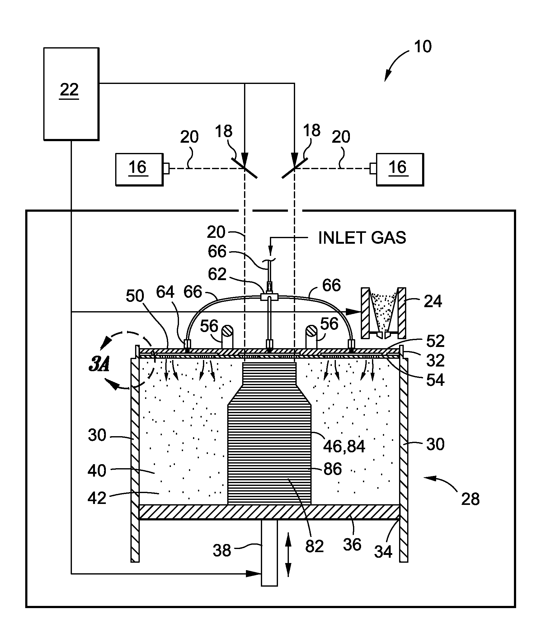
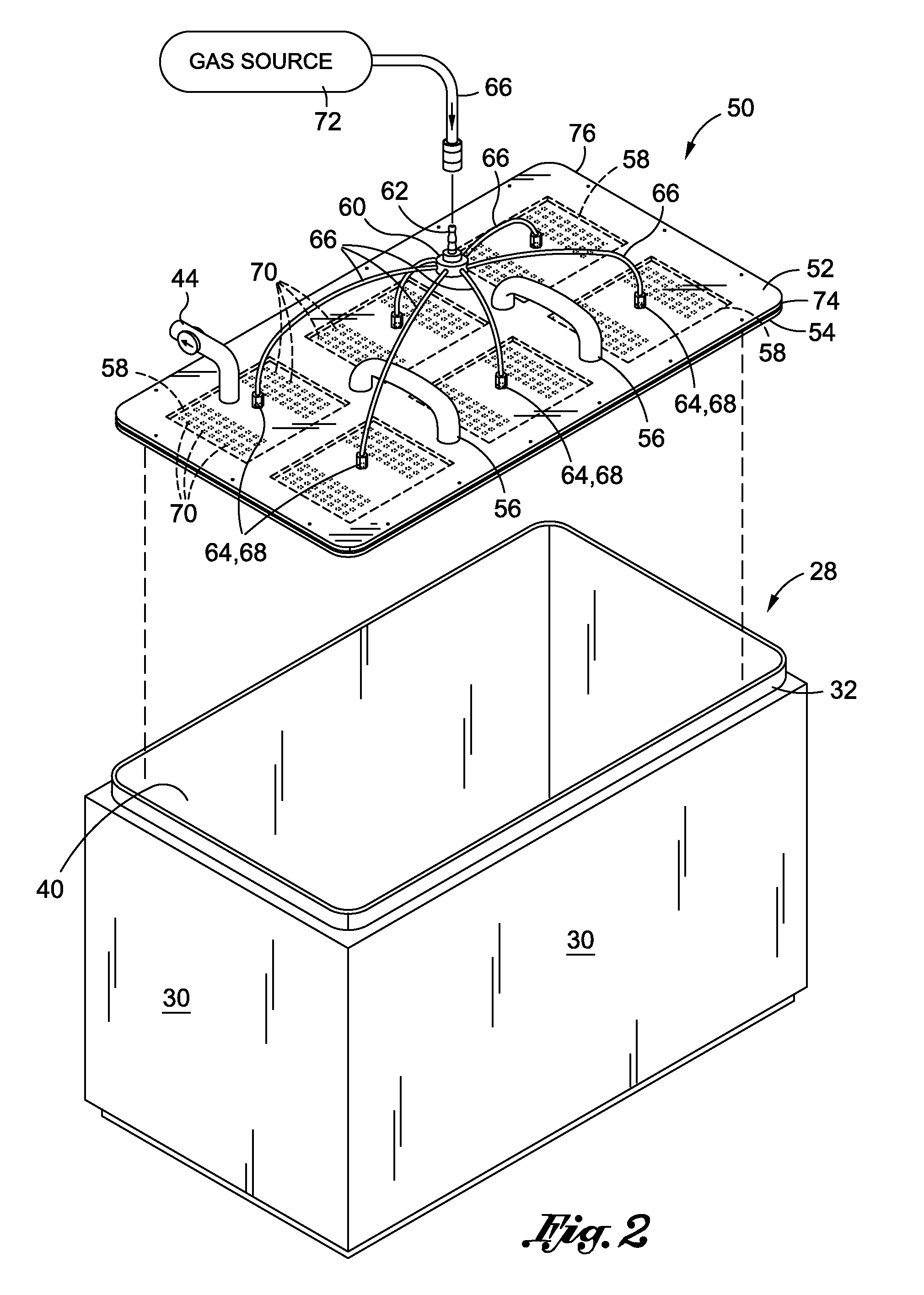
[0014]The technical effects of the embodiments disclosed include the capability for minimizing or preventing infusion of oxygen into the build part with the build frame being removed from the SLS process chamber. In this manner, the cap assembly permits fabrication in the SLS apparatus using a second build frame while the initial build frame cools down outside of the SLS apparatus. The cap assembly may comprise at least one and, more preferably, a plurality of gas lines which are fluidly connectable to the gas inlets. The gas inlets are preferably substantially uniformally distributed throughout the plate assembly in order to allow for even distribution of inert gas such as nitrogen (N2) into the part cake following completion of the build part.
[0016]The cap assembly is specifically configured to sealingly engage an interior surface of side walls that make up the build frame. The cap assembly is preferably configured to be movable vertically within the build frame. The cap assembly also preferably includes a distribution fitting which is configured to be connectable to the gas ports via the gas lines. The distribution fitting is preferably configured as a one-way fitting and, more preferably, is a quick disconnect type fitting wherein the valve is oriented to prevent intrusion of oxygen into the gas lines but allowing inert gas (e.g., nitrogen gas) to flow into the build frame when the distribution fitting is connected to a gas source such as a gas bottle, gas tank or compressor. The gas source is configured to be connectable to the distribution fitting (e.g., via the one-way quick disconnect fitting) for delivering gas to the gas lines.
[0019]Following completion of the build part, the build frame is covered with the cap assembly and gas is delivered to the build volume through the gas lines whereafter the gas is distributed to the part cake through the gas inlets. The delivery of gas to the build volume prevents infusion of oxygen into the build part which prevents oxidation thereof. Excess pressure within the build volume may be vented through the one-way bleed valve or through the seal of the cap assembly or bottom plate of the build frame.
[0021]Advantageously, the ability to use Nylon 11 as the powder material provides a significant cost reduction compared to Nylon 12 material by obviating the need for anti-oxidants. Furthermore, the ability to use Nylon 11 results in finished build parts having improved mechanical properties compared to parts fabricated of Nylon 12 material.

Problems solved by technology

Unfortunately, once the build part is completed, it is desirable to prevent the infusion of oxygen into the part cake which can cause oxidation of the build part.
Oxidation may be undesirable the build part may be adversely affected and the build part may take on a brownish coloring.
Unfortunately, the cool down period can last up to several days during which time the SLS machine is unavailable for fabricating additional parts.
Unfortunately, Nylon 12 powder is relatively expensive due to the addition of such anti-oxidants.
The relatively high cost of Nylon 12 powder increases the end cost of parts as compared to other nylon grades such as Nylon 11 which lacks anti-oxidant agents but which exhibits improved mechanical properties.
Another drawback associated with the use of Nylon 12 is that certain SLS machine manufacturers employ a micro-chipping technique with the powder material.
In this manner, purchasers of the SLS machines must also typically purchase the micro-chipped powder at increased cost to the purchaser.
Other grades of nylon are commercially available but lack the microchip mechanisms.
Unfortunately, in order to make effective use of Nylon 11 in SLS manufacturing, methods must be employed to prevent oxidation of the build part.
Unfortunately, the addition of anti-oxidant agents increases costs and production time due to the additional processing.
Unfortunately, as was earlier mentioned, doing so would prevent SLS fabrication during the 3-4 day cool down period resulting in an underutilization of the SLS machine.

Method used


Image

  • Purge and sealant cap for selective laser sintering build frame
  • Purge and sealant cap for selective laser sintering build frame
  • Purge and sealant cap for selective laser sintering build frame

Examples


Embodiment Construction

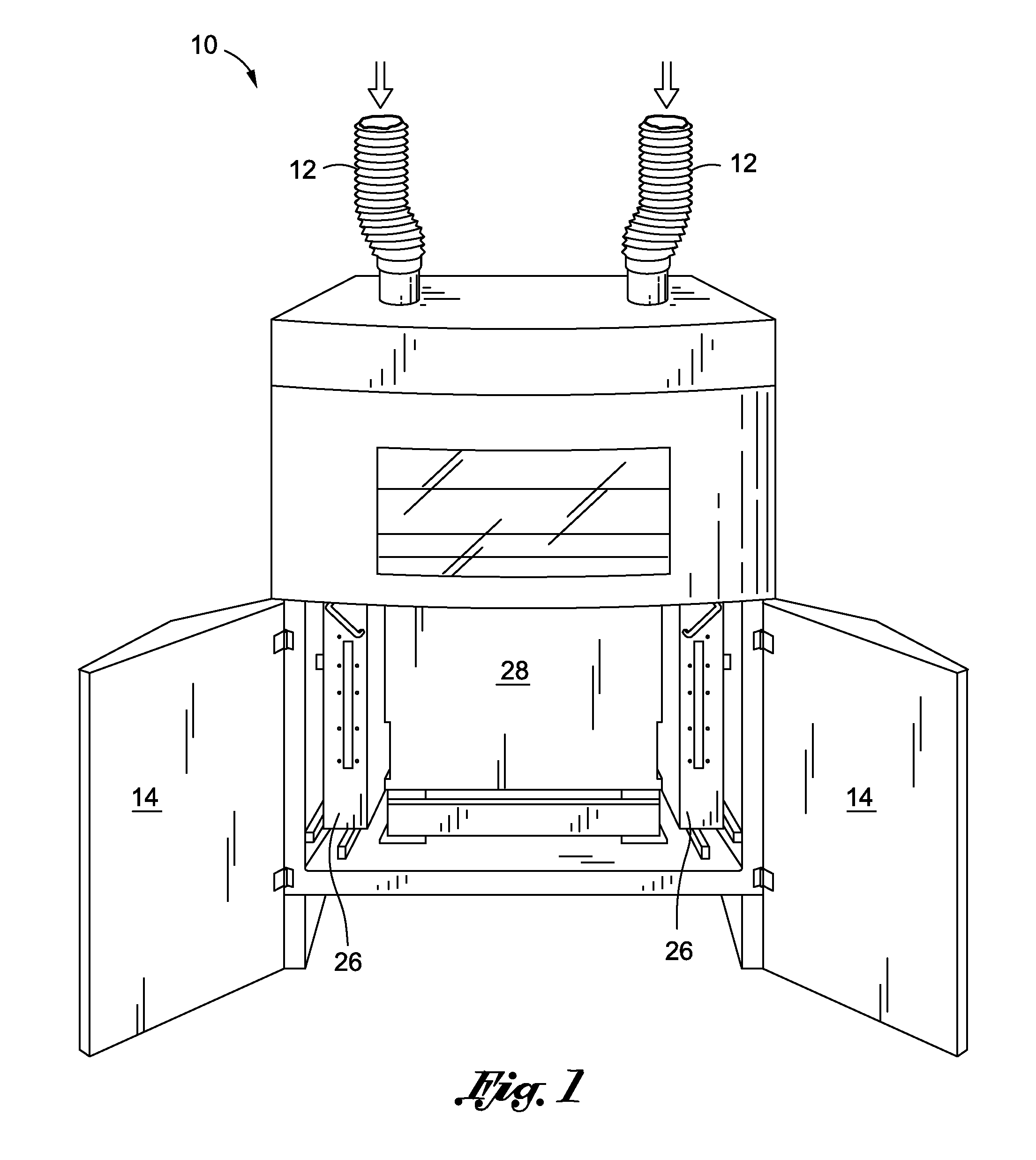
[0037]Referring now to the drawings wherein the showings are for purposes of illustrating preferred and various embodiments of the disclosure only and not for purposes of limiting the same, FIG. 1 is a perspective illustration of a selective laser sintering (SLS) apparatus 10 which may be adapted to removably receive a build frame 28 therewithin. In one embodiment, the SLS apparatus 10 illustrated in FIG. 1 may be similar to that which is disclosed in U.S. Pat. No. 7,153,463 issued to Leuterer et al. on Dec. 26, 2006, the entire contents of which is incorporated by reference herein. As can be seen in FIG. 1, the build frame 28 can be seen installed in a process chamber of the SLS apparatus 10 wherein the process chamber is exposed upon opening of a pair of doors 14.

[0038]In one embodiment, the SLS apparatus 10 may be configured such that the build frame 28 may be removably inserted or docked inside the SLS apparatus 10 (e.g., process chamber) such as via the use of a forklift to mov...


PUM

PropertyMeasurementUnit
tensile strengthaaaaaaaaaa
volumeaaaaaaaaaa
shapesaaaaaaaaaa

Abstract

A selective laser sintering apparatus is adapted contain or receive a build frame and comprises a cap assembly which includes a removable plate assembly having at least one gas inlet formed therein. The removable plate assembly sealingly covers the build frame. The cap assembly further comprises at least one gas line fluidly connectable to the gas inlet via a gas port to deliver inert gas to the interior of the build frame. The plate assembly comprises upper and lower plates defining a spacing therebetween. A seal extends around a periphery of the upper and lower plates and is sandwiched therebetween to enclose the spacing. The lower plate has a plurality of gas inlets formed therein which are in fluid communication with the spacing such that inert gas may be delivered to the build volume while the cap assembly is installed thereupon.

Description

CROSS-REFERENCE TO RELATED APPLICATIONS[0001](Not Applicable)STATEMENT RE: FEDERALLY SPONSORED RESEARCH / DEVELOPMENT[0002](Not Applicable)FIELD[0003]The present disclosure relates generally to rapid prototyping and manufacturing and, more particularly, to a purge and sealant cap assembly for use on a build frame of a selective laser sintering apparatus.BACKGROUND[0004]Selective laser sintering (SLS) is a well-known process for rapidly producing three-dimensional objects from a variety of powder materials. Initially intended for fabricating prototype parts, SLS is now commonly used to fabricate end-use parts in a cost-effective and economical manner and with a high degree of accuracy. For example, SLS is used to fabricate ducting for environmental control systems such as for aircraft due to the lack of geometry constraints when forming such ducting. For example, ducting may have complex curvatures, shapes and / or intricate surface features that can readily be formed using SLS technolog...

Claims


Application Information

Patent Timeline
Patent Type & Authority Applications(United States)
IPC IPC(8): B29C35/08B23K26/12
CPCB29C67/0085B33Y10/00B33Y40/00B33Y30/00B29C64/371B29C64/25
Inventor DIETRICH, DAVID M.
Owner THE BOEING CO
Learn More