Ceramic spark plug insulator and method of making

a ceramic and spark plug technology, applied in the manufacture of spark plugs, sparking plugs, machines/engines, etc., can solve the problems of insufficient manufacturing technology of conventional spark plug insulators, high-purity alumina is difficult to process, and the dielectric strength of ceramics is affected, so as to achieve exceptional electrical properties and reduce density. , the effect of high density

Inactive Publication Date: 2009-10-15
FEDERAL MOGUL IGNITION
View PDF17 Cites 20 Cited by
  • Summary
  • Abstract
  • Description
  • Claims
  • Application Information

AI Technical Summary

Benefits of technology

[0014]The components that are assembled to form the spark plug insulator can be made by any of the commonly used processes used in ceramics. Extrusion is a very efficient method of forming the type of cylindrical components that are used in the present invention. Extruded parts are easily formed and do not have a relic structure from compacted granular material as is found in dry pressed insulators. Extrusion also produces parts of very uniform density. Some of the alumina ceramic parts that have been measured to have the highest dielectric strength were formed by extrusion. Extruded parts are formed to close tolerances on the inside and outside diameters with little waste. By assembling a spark plug insulator by the assembly of two or more extruded tubes that nest within each other, the shape of a spark plug insulator can be obtained. By controlling the density of the individual extruded components, they can be made to shrink during firing in such a way that the joints are strong and gas tight.

Problems solved by technology

However, high-purity alumina is difficult to process, and the manufacturing technology used for conventional spark plug insulators may not be adequate.
The pressing process leaves relics of the spray-dried powder which are known to have a detrimental effect on dielectric strength of the ceramic.
Since the cross sectional area of the pressed blank is not uniform in order to accommodate the shape of the insulator, density gradients may be present so that some regions of the insulator are of lower density and more prone to dielectric failure.
This material is typically reprocessed into subsequent batches of spray-dried powder but is a potential source of contamination.

Method used


Image

  • Ceramic spark plug insulator and method of making
  • Ceramic spark plug insulator and method of making
  • Ceramic spark plug insulator and method of making

Examples


Embodiment Construction

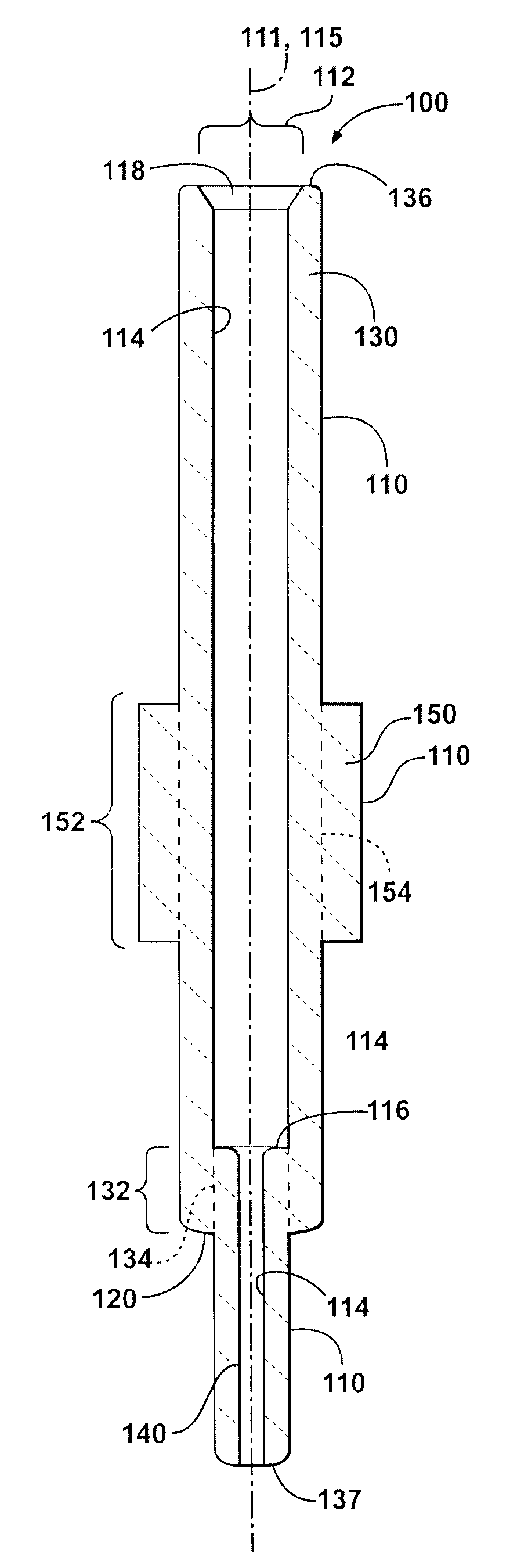
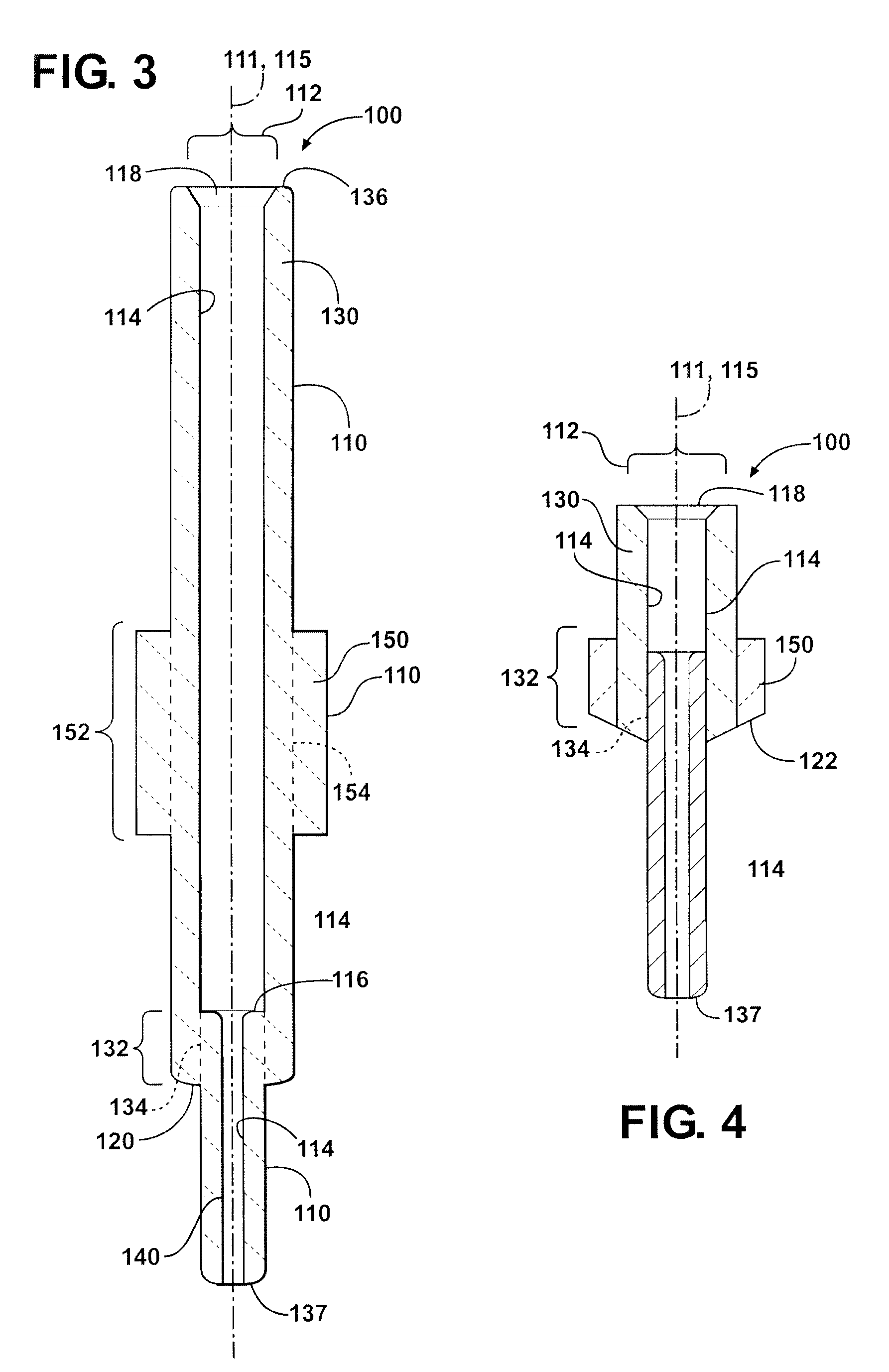
[0027]Referring to FIGS. 3-10, the present invention is a ceramic spark plug insulator 100 which includes a plurality of ceramic tubes 110 which are in nesting engagement and directly bonded to one another by sintering green ceramic preform tubes 210 to form ceramic spark plug insulator 100. Green ceramic preform tubes 210 and the resulting ceramic tubes 110 may have any suitable shape, including a right cylindrical shape which is favorable for obtaining and maintaining nested engagement, and may utilize any suitable outer diameter 112 or outer measurement, including those of a wide variety of conventional spark plug insulators. However, it is believed that the present invention is particularly well adapted as insulators for use with small diameter sparkplugs, such as those having a thread size of M12, M10 and smaller for the reasons set forth herein related to the fact that the ceramic insulators 100 of the invention may be manufactured using materials and processes which will obta...


PUM

PropertyMeasurementUnit
temperatureaaaaaaaaaa
dielectric strengthaaaaaaaaaa
sizeaaaaaaaaaa

Abstract

An insulator for a spark ignition device is disclosed which includes an electrically insulating ceramic core tube having a terminal end, a firing end and an inner bore which extends along a longitudinal bore axis from the terminal end to the firing end and an electrically insulating, ceramic core nose tube having a second outer surface and a second bore where the second outer surface of said ceramic core nose tube is in nested engagement with and directly bonded to the bore of the ceramic core tube proximate the firing end. The insulator also may include a similarly nested and directly bonded shoulder tube on an outer surface of the core tube, or a nested and directly bonded mast tube on an outer surface of the core tube. The ceramics may include alumina-based ceramics, as well other suitable ceramic materials, and the tube may be made from the same ceramic compositions or different ceramic compositions. The invention also includes a method of making the nested tube, directly boded insulators by controlling shrinkage during sintering.

Description

CROSS REFERENCE TO RELATED APPLICATIONS[0001]This application claims priority to Provisional Patent Application No. 61 / 043,746 filed Apr. 10, 2008, the entire disclosure of which is hereby incorporated by reference and relied upon.BACKGROUND OF THE INVENTION[0002]1. Field of the Invention[0003]The present invention relates generally to ceramic insulators, and more particularly to ceramic spark plug insulators and methods of making ceramic spark plug insulators.[0004]2. Related Art[0005]As illustrated in FIG. 1, conventional spark plugs 10 generally utilize a ceramic insulator 12 which is partially disposed within a metal shell 16 and extends axially above the metal shell toward a terminal end 18. A conductive terminal 20 is disposed within a central bore 22 at the terminal end 18. The conductive terminal 20 is part of a conductive center electrode assembly 24 disposed within the central bore 22. At the opposite or firing end 26, a center electrode 28 is disposed within the insulator...

Claims


Application Information

Patent Timeline
Patent Type & Authority Applications(United States)
IPC IPC(8): H01T13/20
CPCH01T21/02H01T13/38
Inventor WALKER, JR., WILLIAM JOHN
Owner FEDERAL MOGUL IGNITION
Why Eureka
Try Eureka