Linear inductive position sensor

a position sensor and inductive technology, applied in the field of position sensors, can solve the problems of increasing the overall fabrication cost of the inductive sensor, increasing the error of the output signal, etc., and achieve the effect of reducing the error amount, reducing the error in the signal from the receiver coil, and simplifying the fabrication of the receiver coil

Active Publication Date: 2009-10-15
KSR IP HLDG
View PDF2 Cites 9 Cited by
  • Summary
  • Abstract
  • Description
  • Claims
  • Application Information

AI Technical Summary

Benefits of technology

[0013]Unlike the previously known receiver coils, however, the first and second loops of the receiver coil are linearly aligned and adjacent with each other along the first direction, i.e. the direction of movement of the coupler element. Such a configuration not only simplifies the fabrication of the receiver coil, but also reduces the amount of error caused by tilting of the coupler element.
[0014]In order to further reduce the error in the signal from the receiver coil caused by tilting of the coupler element, the coupler element optionally is U-shaped so that the coupler element overlies both the top as well as the bottom of the receiver and transmitter coils. Thus, any increase in the inductive coupling caused by tilting of the coupler element on the top of the transmitter and receiver coils is offset by a reduced coupling on the bottom of the transmitter and receiver coils, and vice versa.

Problems solved by technology

This disadvantageously increases the overall fabrication cost of the inductive sensor and also increases the error of the output signal that may be caused by tilting of the coupler element relative to the exciter and receiver coils.

Method used


Image

  • Linear inductive position sensor
  • Linear inductive position sensor

Examples


Embodiment Construction

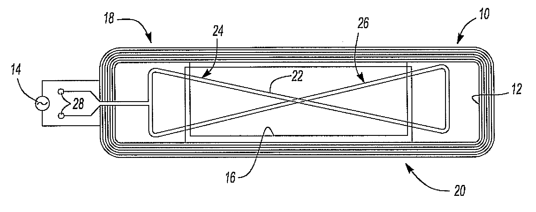
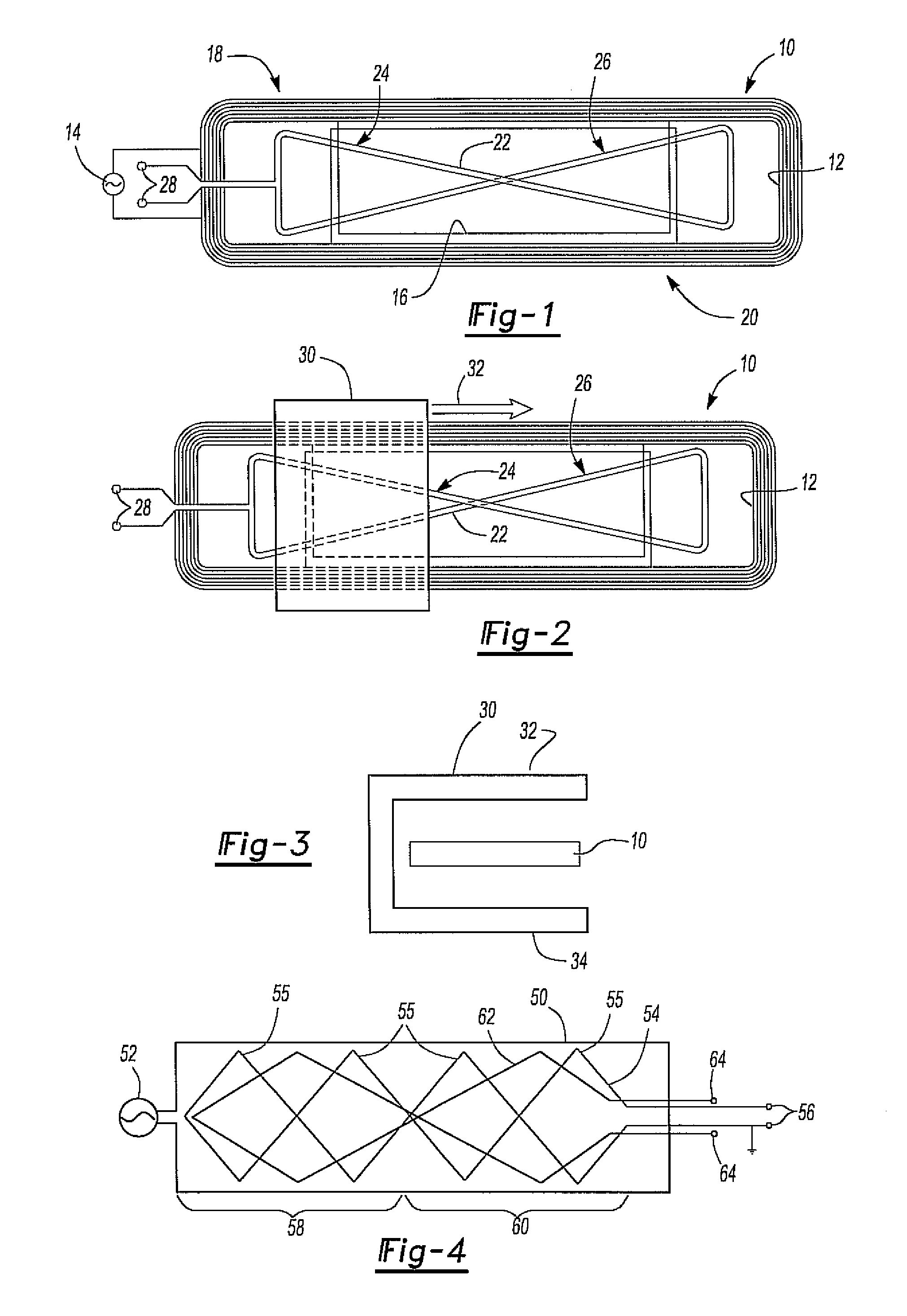
[0020]With reference first to FIG. 1, an improved linear inductive sensor 10 is shown having a multi-loop transmitter coil 12. The loops of the transmitter coil 12 are all wound in the same direction and the transmitter coil is excited by a high frequency AC source 14. For example, for automotive applications, the frequency of the AC source 14 is typically in the range of about 2.4 megahertz.

[0021]A reference coil 16 is also provided so that a portion of the reference coil 16 is wound around each end 18 and 20 of the sensor 10. The reference coil 16 provides a means for compensating for temperature, environmental factors, etc. in the well-known fashion.

[0022]A receiver coil 22 can be contained either partially or entirely within the interior of the transmitter coil 12. The receiver coil 22 is in the form of a bowtie and includes two linearly aligned and adjacent portions 24 and 26. These portions 24 and 26 of the receiver coil 22, furthermore, are oppositely wound from each other.

[0...


PUM


Abstract

A linear position sensor having a transmitter coil which generates electromagnetic radiation when excited by a source of electrical energy and wound in a first direction. A receiver coil is contained within the transmitter coil and the receiver coil includes both a first loop wound in a first direction and a second loop wound in the opposite direction. A coupler element linearly moves along a first direction relative to the transmitter coil which varies the inductive coupling between the transmitter coil and the receiver coil as a function of the linear position of the coupler element to thereby vary the electrical output signal from the receiver coil when excited by the transmitter coil. The first and second loops of the receiver coil are linearly aligned with each other along the first direction.

Description

CROSS REFERENCE TO RELATED APPLICATIONS[0001]This application claims priority of U.S. Provisional Patent Application Ser. No. 61 / 045,014 filed Apr. 15, 2008, which is incorporated herein by reference.BACKGROUND OF THE INVENTION[0002]I. Field of the Invention[0003]The present invention relates generally to position sensors and, more particularly, to a linear inductive position sensor.[0004]II. Description of Related Art[0005]Modern automotive vehicles typically include a plurality of different position sensors which generate an electric signal indicative of the position of the sensor. While some position sensors generate an electrical signal output representative of the rotational position of a sensor element, other position sensors are linear sensors which generate an electrical output signal representative of the linear position of the sensor element.[0006]Many of the previously known sensors are formed on a printed circuit board and include an exciter or transmitter coil which is ...

Claims


Application Information

Patent Timeline
Patent Type & Authority Applications(United States)
IPC IPC(8): G01B7/14
CPCG01B7/003
Inventor ELLIOTT, RYAN W.LEE, JOONG K.SHAO, LINGMIN
Owner KSR IP HLDG
Why Eureka
Try Eureka