Voltage-clamp power converters

a power converter and voltage clamp technology, applied in the field of power converters, can solve the problems of failure of the converter, emi problems, voltage stress may be too high for available semiconductor switches in many other applications, and achieve the effects of reducing input current ripple, reducing emi problems, and improving converter efficiency

Inactive Publication Date: 2009-10-15
NAT TAIWAN UNIV OF SCI & TECH
View PDF10 Cites 48 Cited by
  • Summary
  • Abstract
  • Description
  • Claims
  • Application Information

AI Technical Summary

Benefits of technology

[0017]Accordingly, an object of the present invention is to provide inversion circuits having reduced input current ripple thereby to alleviate the EMI problems and to improve the converter's efficiency.

Problems solved by technology

An issue of concern regarding aforementioned converters is that a magnetizing and the leakage energies stored in the transformer must be taken into consideration during the design of the converter.
Otherwise, these magnetic energies stored in the transformer may cause the failure of the converter.
Another issue of concern regarding aforementioned converters is to alleviate the electromagnetic interference EMI problems.
Part of the EMI problems is caused by the pulsating current ripples, di / dt, in the power converters.
On the contrary, voltage stress may be too high for available semiconductor switches in many other applications.
Consequently, the conduction losses are increased.

Method used


Image

  • Voltage-clamp power converters
  • Voltage-clamp power converters
  • Voltage-clamp power converters

Examples


Embodiment Construction

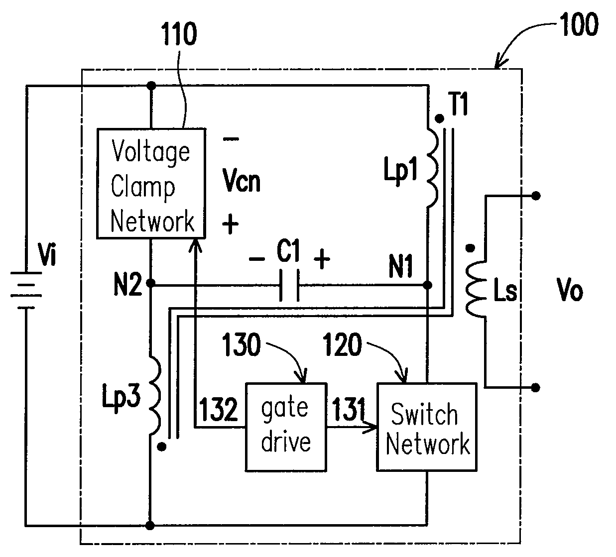
[0035]As illustrated in FIG. 5 is a circuit diagram of the power converter 100 to introduce the broad concept of resetting a transformer by transferring energy to reset winding via the capacitors of the present invention. The circuit used to convert a DC input to an AC output comprises two series circuits, one capacitor C1, and one transformer T1. The transformer T1 has two identical primary windings Lp1 and Lp3 and at least one secondary winding Ls. Both series circuits are connected in parallel with the DC input source Vi. The first series circuit comprises the first transformer primary winding Lp1 and one switch network 120; while the second series circuit comprises the voltage-clamp network 110 and the secondary transformer primary winding Lp3. The switch network 120 comprises at least one semiconductor switch and the voltage-clamp network 110 comprises at least one active or one passive voltage-clamp cell. The active voltage-clamp cell is formed by a MOSFET Sc series-connected ...


PUM


Abstract

Several inversion circuits used to convert a DC input to an AC output comprise two series circuits, at least one clamp capacitor, and at least one transformer. Each of the series circuits is in parallel with the DC input. The first series circuit includes one switch network and at least one transformer primary. The second series circuit includes one voltage-clamp network and at least one transformer primary. At least one clamp capacitor couples the first and the second series circuits, and is attached to each series circuit at a node between the respective transformer primary winding. The voltage-clamp network may be implemented with two of the three sub-circuits connected in series: a diode, a resister-capacitor-diode, and a MOSFET-capacitor.

Description

BACKGROUND OF THE INVENTION[0001]1. Field of Invention[0002]The present invention is related to the field of power converter, and more specifically, to a voltage-clamp method for DC / DC power converters.[0003]2. Description of Related Art[0004]Achieving a higher power density is an endless goal of modern power converter engineers for the crucial applications wherein the allocated space of the power converter is limited. In addition to being highly compact, the power converter has to be able to minimize the power dissipation.[0005]In low-to-medium level power conversion applications, single-ended power converter topology, such as a single-switch forward converter or a single-switch flyback converter, is widely used. It includes an isolation transformer, a switch on a primary side of the transformer, a rectifier and an output filter on a secondary side of the transformer. By way of the on / off control of the power switch, an AC voltage is generated in the transformer primary from input ...

Claims


Application Information

Patent Timeline
Patent Type & Authority Applications(United States)
IPC IPC(8): H02M7/217
CPCH02M1/34H02M3/33538H02M1/342Y02B70/10
Inventor LEU, CHING-SHAN
Owner NAT TAIWAN UNIV OF SCI & TECH
Why Eureka
Try Eureka