

Carbon structure manufacturing device and manufacturing method
a manufacturing device and carbon structure technology, applied in the direction of catalyst activation/preparation, metal/metal-oxide/metal-hydroxide catalysts, metal/metal-oxide catalysts, etc., can solve the problems of carbon structure damage, carbon structure damage, carbon structure damage,
- Summary
- Abstract
- Description
- Claims
- Application Information
AI Technical Summary
Benefits of technology
Problems solved by technology
Method used
Image

Examples
first embodiment
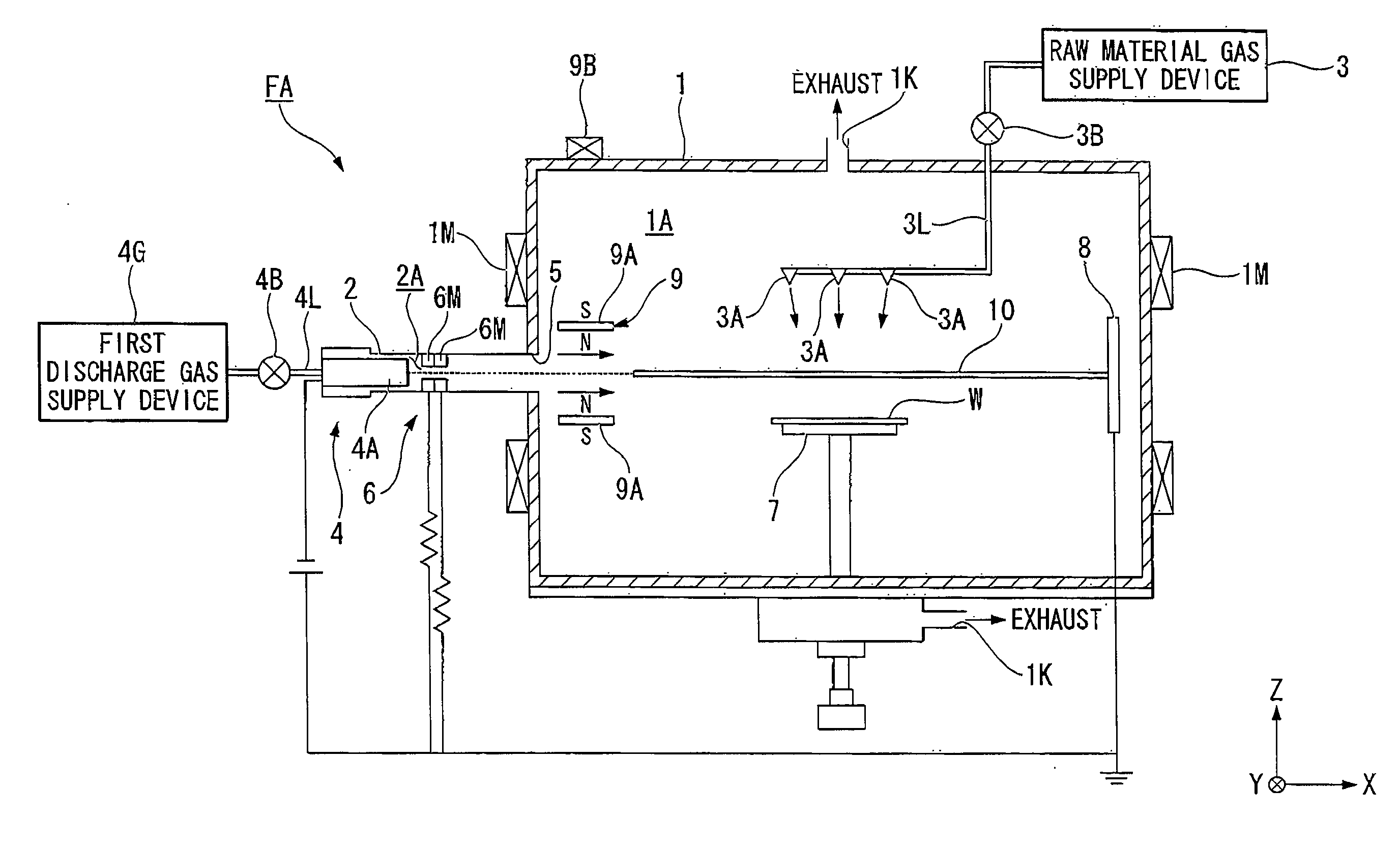
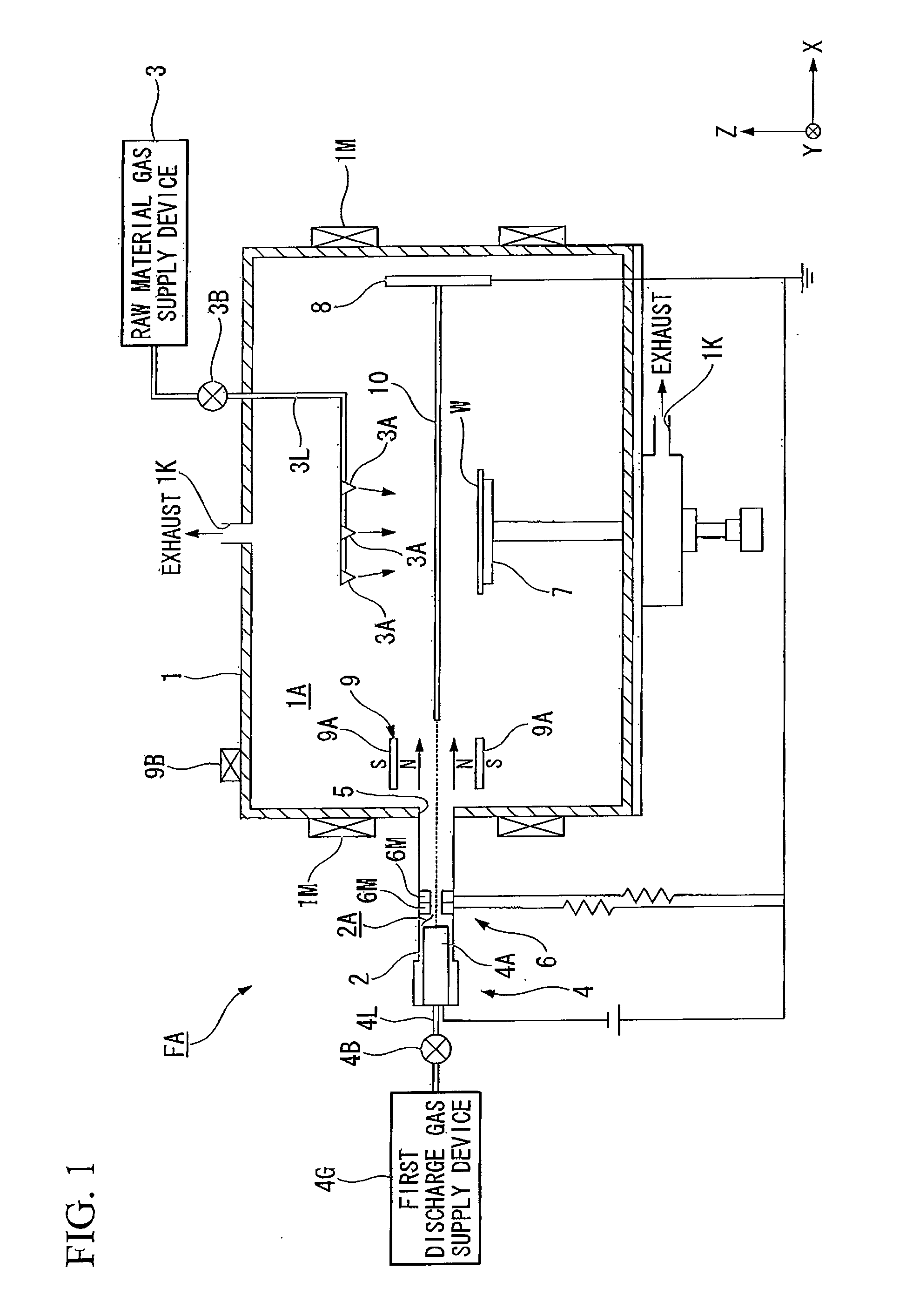
[0053]A first embodiment of the invention is explained. FIG. 1 is a summary view of the configuration of the carbon structure manufacturing device FA of the first embodiment of the invention. Carbon structures include so-called carbon nanostructures. Carbon nanostructures include, for example, carbon nanowalls, carbon nanotubes, carbon nanofibers, carbon nanoflakes, and carbon nanosheets.
[0054]In this embodiment, an explanation is given for an example in which the manufacturing device FA manufactures carbon nanostructures by forming carbon nanostructures on a substrate W; however, the invention is not limited to such a configuration. The manufacturing device FA can manufacture any structures including carbon. That is, carbon structures (carbon nanostructures) which can be formed by the manufacturing device PA are not limited to those described above, but may be any arbitrary carbon structure (carbon nanostructure).
[0055]In FIG. 1, the manufacturing device FA comprises a first chambe...
second embodiment
[0087]Next, a second embodiment of the invention is explained. A characteristic of the second embodiment is the fact that the manufacturing device FA comprises a sputtering device 11, which has a holding member 12 to hold a target material T so as to be positioned in the first space 1A, which bombards the target material T with ion particles generated based on the inert gas in the plasma introduced into the first space 1A, and so causes sputtered particles to be emitted from the target material T in order to form a metal film and / or fine catalyst particles on the substrate W. That is, in the above-described first embodiment, carbon structures are formed based on a so-called plasma CVD method, but in the second embodiment, in addition to the operation of forming carbon structures based on the plasma CVD method, an operation is executed to form metal film and / or fine catalyst particles based on a so-called sputtering method. In the following explanation, constituent portions which are...
third embodiment
[0102]Next, a third embodiment of the invention is explained. In the above-described second embodiment, power is applied to the electrode 12A which holds the target material T, a plasma generation region PU′ is formed in the first space 1A, and a metal film is formed; however, as shown in FIG. 5A, plasma generated by the plasma generation device 4 may be introduced into the first space 1A in which the target material T is positioned, and the introduced plasma (sheet plasma 10) may be used in sputtering of the target material T. By this means, a metal film can be formed on the substrate W.
[0103]In this embodiment, the second discharge gas supply device 14 may be omitted. When, for the gas supply quantity from the first discharge gas supply device 4G needed to attain the pressure as necessary to generate plasma in the second space 2A, the pressure in the first space 1A cannot reach the prescribed pressure necessary for sputtering, the second discharge gas supply device 14 may be acces...
PUM
| Property | Measurement | Unit |
|---|---|---|
| Pressure | aaaaa | aaaaa |
| Electrical conductor | aaaaa | aaaaa |
Abstract
Description
Claims
Application Information