
System and method for self-contained structural health monitoring for composite structures

a composite structure and self-contained technology, applied in the direction of mechanical measurement arrangements, mechanical roughness/irregularity measurements, instruments, etc., can solve the problems of composite part cracking, high cost, and high labor intensity

Active Publication Date: 2009-10-15
SPIRIT AEROSYSTEMS
View PDF19 Cites 37 Cited by
  • Summary
  • Abstract
  • Description
  • Claims
  • Application Information

AI Technical Summary

Benefits of technology

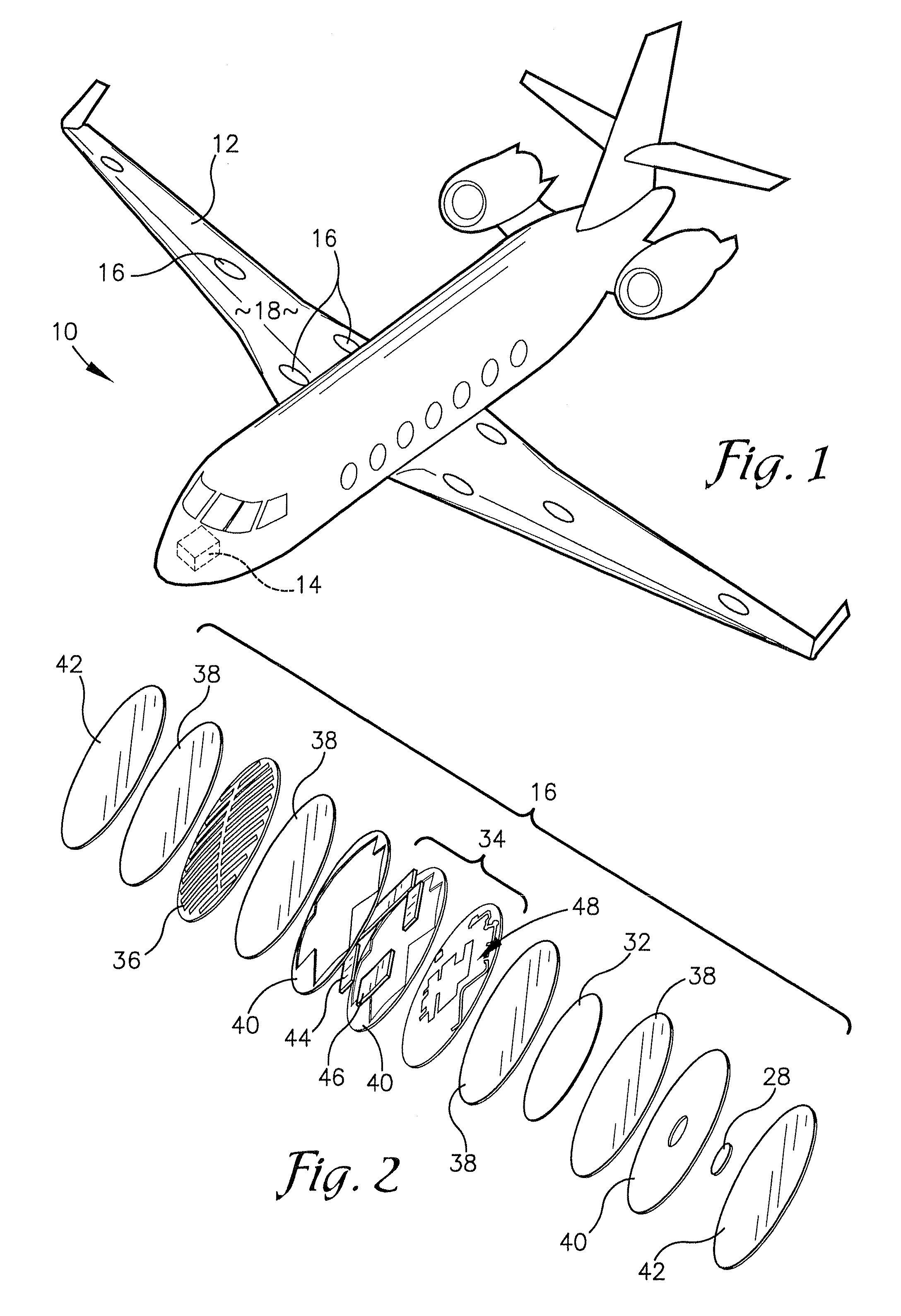
[0015]Furthermore, outer carbon fiber plies of the sensor wafers may be bonded to the surface of a composite part and bonded thereto via a composite curing process. Subsequently, the sensor wafers may be covered with an epoxy-based protective coating to shield them from environmental elements that may damage the sensor wafers. These and other important aspects of the present invention are described more fully in the detailed description below.
[0016]This Summary is provided to introduce a selection of concepts in a simplified form that are further described below in the Detailed Description. This Summary is not intended to identify key features or essential features of the claimed subject matter, nor is it intended to be used to limit the scope of the claimed subject matter.

Problems solved by technology

Historically, such detection has been done manually, but this is extremely time-consuming and often ineffective because many types of damage and / or deterioration is difficult to detect with the naked eye.
However, because the sensors and wires are glued to the exterior of the aircraft structure, they are susceptible to damage.
However, studies have shown that sensors embedded within a composite laminate can cause resin buildup in the vicinity of the sensor, which can initiate cracking in the composite part.
However, such pockets are difficult to manufacture and can decrease the stress allowed for a given composite part due to the cuts made in the fiber in the local area of each sensor.
Embedding the sensors in a composite part and connecting the grid of sensors together or to a central bus can also slow down the manufacturing process.
There also exists a risk that the subsequent tows would dislodge sensors or wires.
Then, if a sensor is faulty, there is no simple way to remove and replace the embedded sensor without affecting the structural integrity of the composite part.
Additionally, routing and gluing wires and connectors around complex structures and systems can also be problematic.
Therefore, some sensors must send the wireless signal farther, causing those sensors to consume a greater amount of power.
This need for power limits how small the batteries for such wireless sensors may be.
Additionally, the farther that each wireless sensor must send a signal, the more likely it is that the signal may experience some type of interference.

Method used


Image

  • System and method for self-contained structural health monitoring for composite structures
  • System and method for self-contained structural health monitoring for composite structures
  • System and method for self-contained structural health monitoring for composite structures

Examples


Embodiment Construction

[0025]The following detailed description of the invention references the accompanying drawings that illustrate specific embodiments in which the invention can be practiced. The embodiments are intended to describe aspects of the invention in sufficient detail to enable those skilled in the art to practice the invention. Other embodiments can be utilized and changes can be made without departing from the scope of the present invention. The following detailed description is, therefore, not to be taken in a limiting sense. The scope of the present invention is defined only by the appended claims, along with the full scope of equivalents to which such claims are entitled.

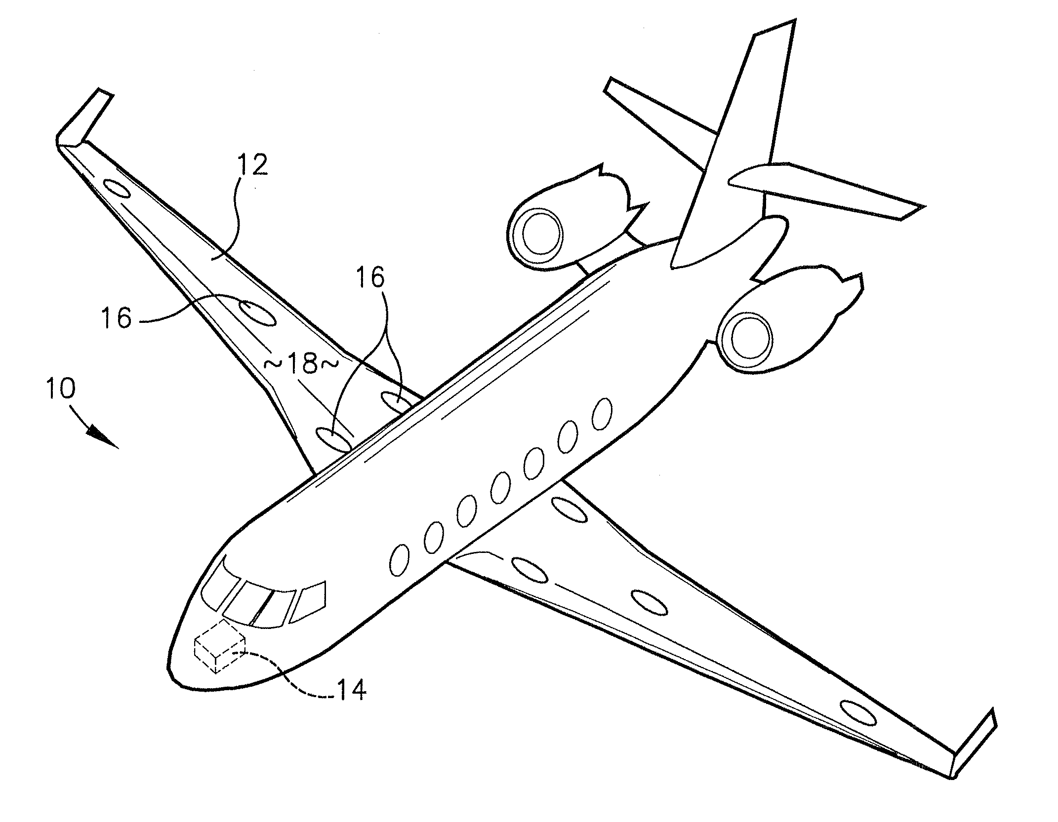
[0026]As illustrated in FIG. 1, various embodiments of the invention provide a wireless, self-contained Structural Health Monitoring (SHM) system 10 for monitoring the structural health of at least one physical structure 12, such as composite parts of an aircraft. The SHM system 10 has a central data acquisition module ...


PUM


Abstract

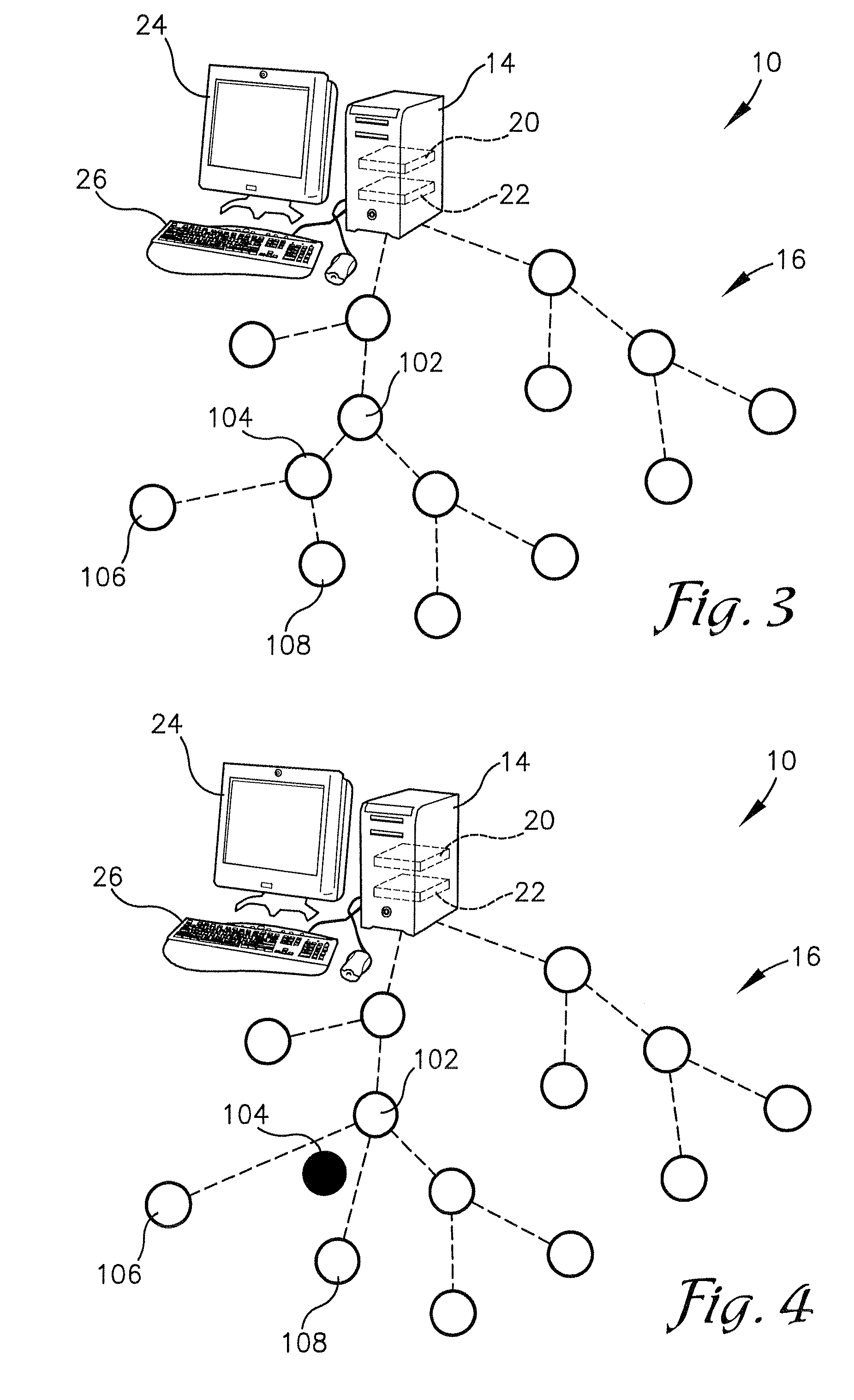
A system and method for structural health monitoring (SHM) of a physical structure, such as an aircraft component. The system may comprise a central data acquisition module and a plurality of wireless, self-contained sensor wafers bonded to a surface of the physical structure. The central data acquisition module and the sensor wafers may be communicably coupled in a hierarchical order. If any of the sensor wafers detects a structural fault, it may be stored in a memory of the central data acquisition module for retrieval by maintenance personnel. If one or more of the sensor wafers malfunctions, the central data acquisition module may reconfigure the hierarchical order in which the sensor wafers communicate to exclude the malfunctioning sensor wafer or wafers. The sensor wafers may include a sensor, circuitry, a wireless antenna, and a power source.

Description

RELATED APPLICATIONS[0001]This nonprovisional patent application claims priority benefit, with regard to all common subject matter, of earlier-filed U.S. provisional patent application titled “A Self-Contained Structural Health Monitoring System For Aircraft Composite Panels”, Ser. No. 61 / 045,153, filed Apr. 15, 2008. The identified earlier-filed application is hereby incorporated by reference in its entirety into the present application.BACKGROUND[0002]1. Field[0003]The present invention relates to structural health monitoring (SHM) of aircraft parts. More particularly, the present invention relates to wireless, self-contained sensors communicating hierarchically with a central data acquisition module for monitoring the structural health of a composite part.[0004]2. Related Art[0005]Detection of structural damage or deterioration of various aircraft components is critical to insuring the safety of all occupants and cargo on board. Historically, such detection has been done manually...

Claims


Application Information

Patent Timeline
Patent Type & Authority Applications(United States)
IPC IPC(8): G01B5/28
CPCG01M5/00G01B7/16
Inventor LOOMIS, KEVIN S.TADAYON, FARHAD J.
Owner SPIRIT AEROSYSTEMS
Learn More