Method and apparatus for simulating packet delay variation of a multi-switch network

a multi-switch network and packet delay technology, applied in data switching networks, instruments, pulse characteristics measurements, etc., can solve problems such as packet delay variations, variable delay, packet delay variations, etc., and achieve significant longer packet delays

Inactive Publication Date: 2009-10-15
INTEL CORP
View PDF8 Cites 8 Cited by
  • Summary
  • Abstract
  • Description
  • Claims
  • Application Information

AI Technical Summary

Benefits of technology

[0012]In some cases, the packet delay variation generator uses a Gamma distribution to describe the low delay portion of measured packet data and one or more uniform distributions to describe the long-tail portion of the measured packet data. In this way, the simulation system more accurately models and / or simulates the real network traffic.

Problems solved by technology

In each network switch, packets are queued or buffered, resulting in variable delay.
Packet delays and delay variations are caused by the queuing and scheduling processes of packets through intermediate packet switches.
Though this sharing provides resource efficiency (e.g., low packet delays) for the majority of the packets, it often results in significantly longer packet delays during times of high traffic bursts and / or when large packets pass through the switches.
These packets typically have larger delays and higher delay variation.
This delay may be caused by a single switch or may be the result of multiple cascaded switches.
Though PDV is generally modeled as having a Gaussian probability density function (PDF), this modeling may be inappropriate for stress-testing adaptive timing recovery algorithms.
However, these network emulators do not take into account how packet delays change with varying traffic load.
That is, they do not address the true delay variation of packets in networks, which tends to follow a long-tailed probability density function for packet flowing over the same path.

Method used


Image

  • Method and apparatus for simulating packet delay variation of a multi-switch network
  • Method and apparatus for simulating packet delay variation of a multi-switch network
  • Method and apparatus for simulating packet delay variation of a multi-switch network

Examples


Embodiment Construction

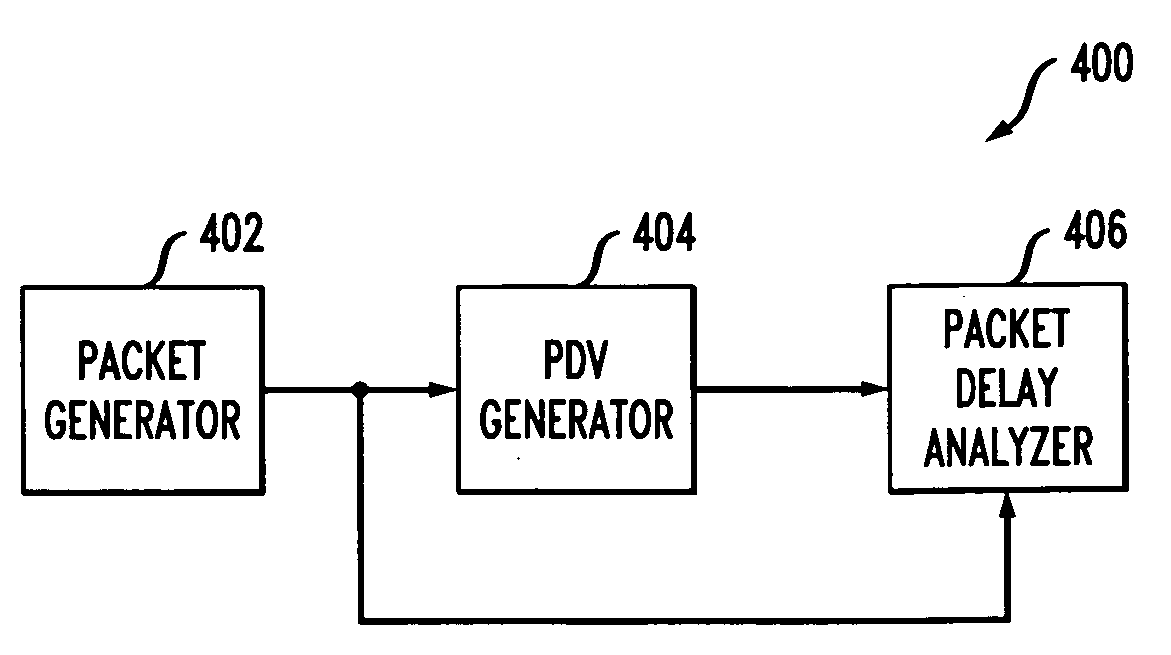
[0032]The present invention relates generally to modeling packet delay variation (PDV) over multi-switched networks and more specifically to modeling PDV using a combination of deterministic and statistical delay processes.

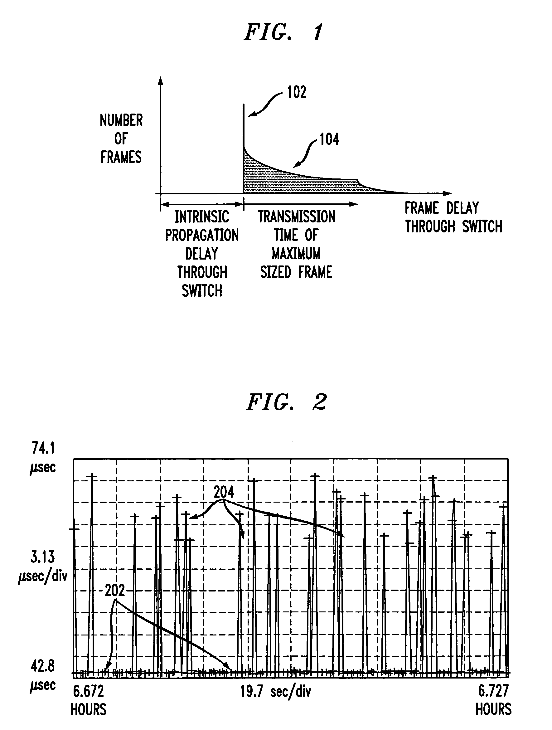
[0033]Generally, a packet delay-step process for each packet delay band (e.g., similar to the low packet-delay band 202 and a high packet-delay band 204 described above) may be controlled by different statistical models. For example, by using a narrow-width Gamma probability density function (PDF) to model PDV in the low-delay band, the statistical delay variation may be precisely limited to this defined range. Likewise, by using a wide-width uniform PDF to model the high delay band (e.g., the “long-tail”) PDV, the packet delays may be allowed to vary over a much wider delay range per the defined limits of this PDF.

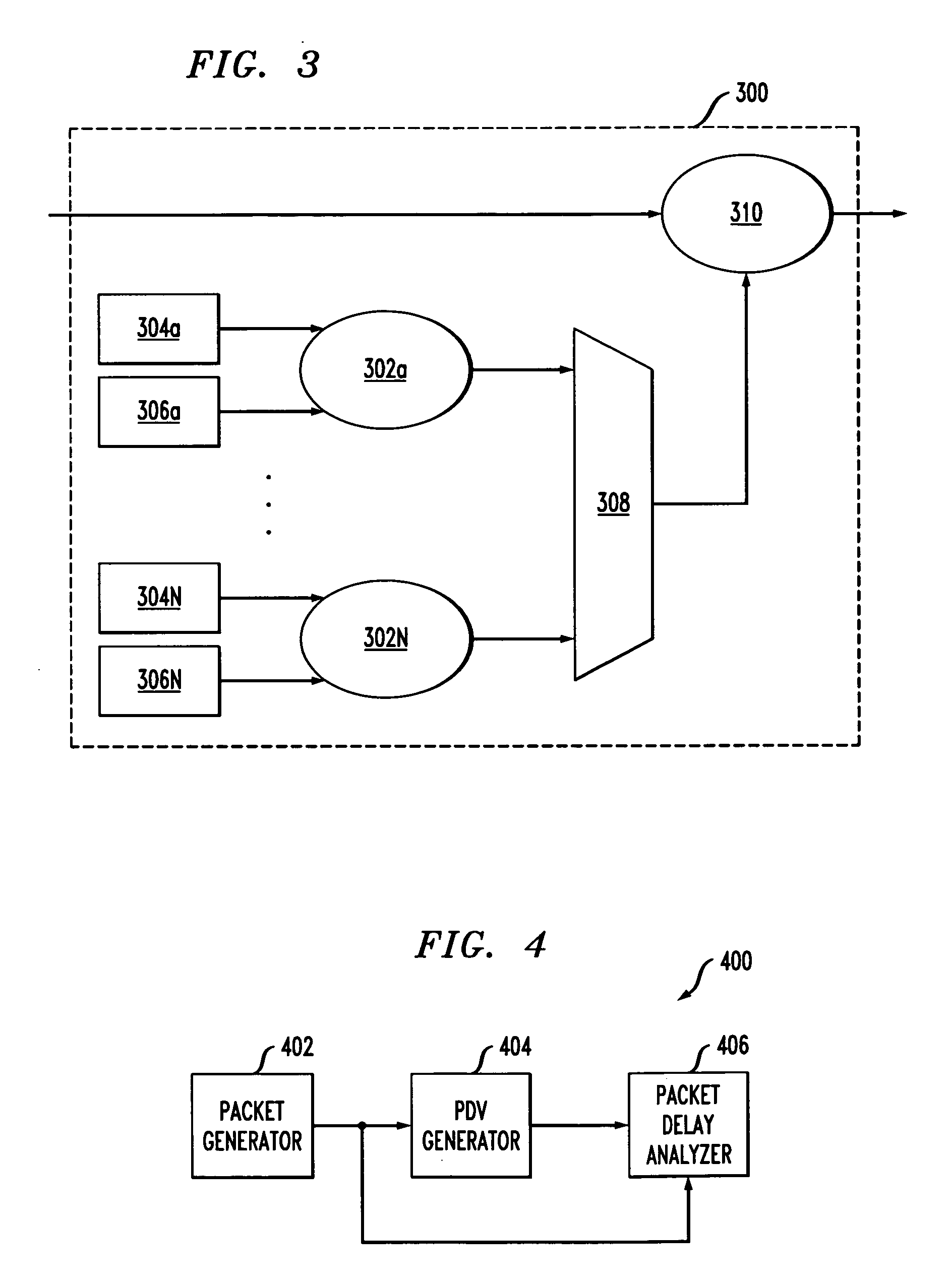
[0034]FIG. 3 depicts a PDV generator 300 according to an embodiment of the present invention. The PDV generator 300 may be used in the generation (e.g....


PUM


Abstract

A packet delay variation simulation system has a packet generator, a packet delay variation generator, and a packet delay analyzer to analyze delayed packets. The packet delay variation generator has multiple delay distribution modules that use both a deterministic delay process and a statistical delay process packet for determining a packet's delay. The packet delay variation generator may utilize different probability density functions to describe various portions of measured packet data. That is, measured packet delay information is analyzed and information from this analysis is used to construct a total delay model for a network. The delay may include a pre-determined deterministic delay offset as well as one or more variable statistical delay offsets.

Description

CROSS REFERENCE TO RELATED APPLICATIONS[0001]This application is related to co-pending U.S. patent application Ser. No. 12 / 074,154, Attorney Docket No. Bedrosian 14, entitled “Simulating Packet Delay Variation Using Step-Target Delay Method,” filed Feb. 29, 2008, co-pending U.S. patent application Ser. No. 12 / 074,031, Attorney Docket No. Bedrosian 12, entitled “Method and System for Generating Packet Delay Variation with a Uniform Distribution,” filed Feb. 29, 2008, U.S. patent application Ser. No. 12 / 074,155, Attorney Docket No. Bedrosian 13, entitled “Connectionless Configurations for Stress Testing Timing and Synchronization in Data Packet Networks,” filed Feb. 29, 2008, and U.S. patent application Ser. No. 12 / 074,043, Attorney Docket No. Bedrosian 11, entitled “Derivative Packet Delay Variation as a Metric for Packet Timing Recovery Stress Testing,” filed Feb. 29, 2008, each of which incorporated herein by reference.BACKGROUND OF THE INVENTION[0002]In multi-switch networks, pack...

Claims


Application Information

Patent Timeline
Patent Type & Authority Applications(United States)
IPC IPC(8): G06G7/62G06F17/10
CPCH04L43/50H04L12/2697
Inventor BEDROSIAN, PAUL STEPHAN
Owner INTEL CORP
Why Eureka
Try Eureka