Automatic solid Phase Microextraction (Spme) Sampling Apparatus

a sampling apparatus and solid phase technology, applied in the direction of components, withdrawing sample devices, surface/boundary effects, etc., can solve the problems of inability to determine automated analysis, inability to use several fibers simultaneously in a single working session, and limited automatic extraction/injection procedures

Active Publication Date: 2009-10-22
DEGLI ESPOSTI FILIPPO +1
View PDF5 Cites 20 Cited by
  • Summary
  • Abstract
  • Description
  • Claims
  • Application Information

AI Technical Summary

Benefits of technology

[0007]The object of the present invention is to provide an automatic sampling apparatus for use in solid phase microextraction (SPME) that enables the automatic replacement of the SPME probes on the autosampler arm.

Problems solved by technology

Using the SPME method, the automation of the extraction / injection procedure is limited because the operator has to take action every time the probe installed on the autosampler arm needs to be changed.
For instance, automated analysis is not feasible for determining airborne pollutants when, during a given sampling campaign, the technician appointed to collect the samples is likely to return to the laboratory with a large number of probes whose fibers have been exposed to the environment being monitored.
Using the holders currently available on the market, SPME fibers can be used on some autosamplers, but several fibers cannot be used simultaneously in a single working session unless the autosampler is stopped and an operator is on hand to change the probe.
This represents a serious drawback of the SPME method because, if, for instance, there are two sets of samples on which two substances have to be assayed, which requires the use of two different SPME fibers, then the first set of samples has to be analyzed first, then the fiber has to be changed before the second set of samples can be analyzed.
This problem is already important when it comes to assays on liquid or biological samples, but is further amplified in the case of environmental sampling, when the lack of a fully automated procedure considerably extends the time it takes to perform the analyses.

Method used


Image

  • Automatic solid Phase Microextraction (Spme) Sampling Apparatus
  • Automatic solid Phase Microextraction (Spme) Sampling Apparatus
  • Automatic solid Phase Microextraction (Spme) Sampling Apparatus

Examples


Embodiment Construction

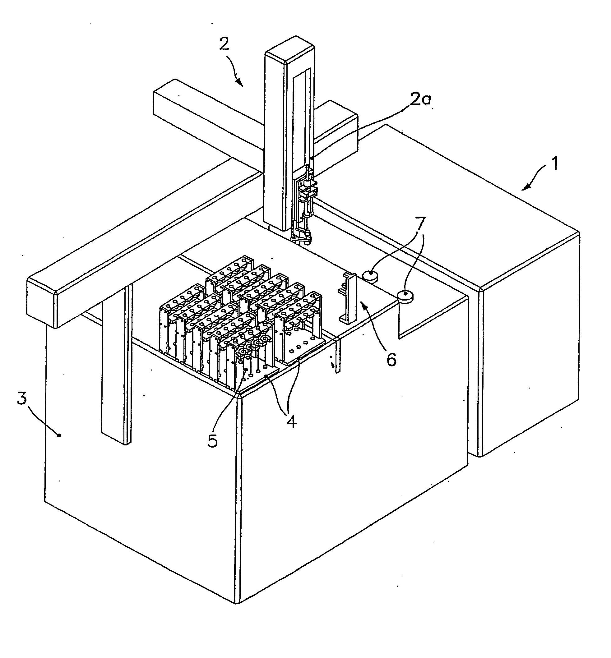
[0028]The apparatus according to the present invention is schematically shown in FIG. 1, in association with a detector for gas chromatographic analyses (a mass spectrometer, for example) generically indicated by the numeral 1 and comprises a robotic autosampler arm 2 supported by the gas chromatograph, on which one or more trays 4 for supporting the probes containing the SPME fibers (indicated by the numeral 5) are neatly arranged. These probes may, for instance, come from a campaign of environmental analyses and are ready for gas chromatographic analysis. Alongside the trays 4, there is a bracket for transferring the probes 5 (generically indicated by the numeral 6) that is described in more detail later on. The numeral 7 indicates two injectors of the gas chromatographic apparatus.

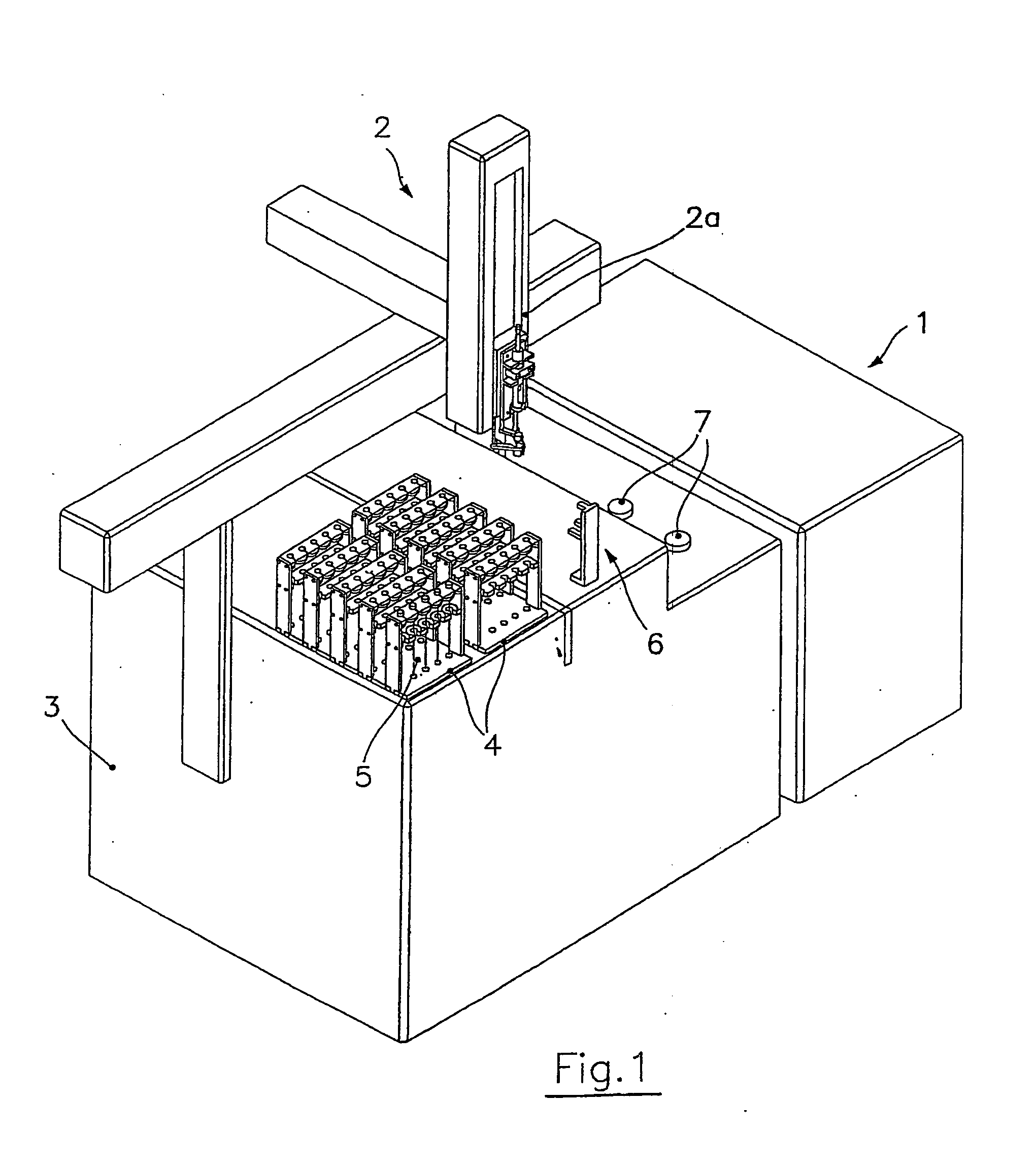
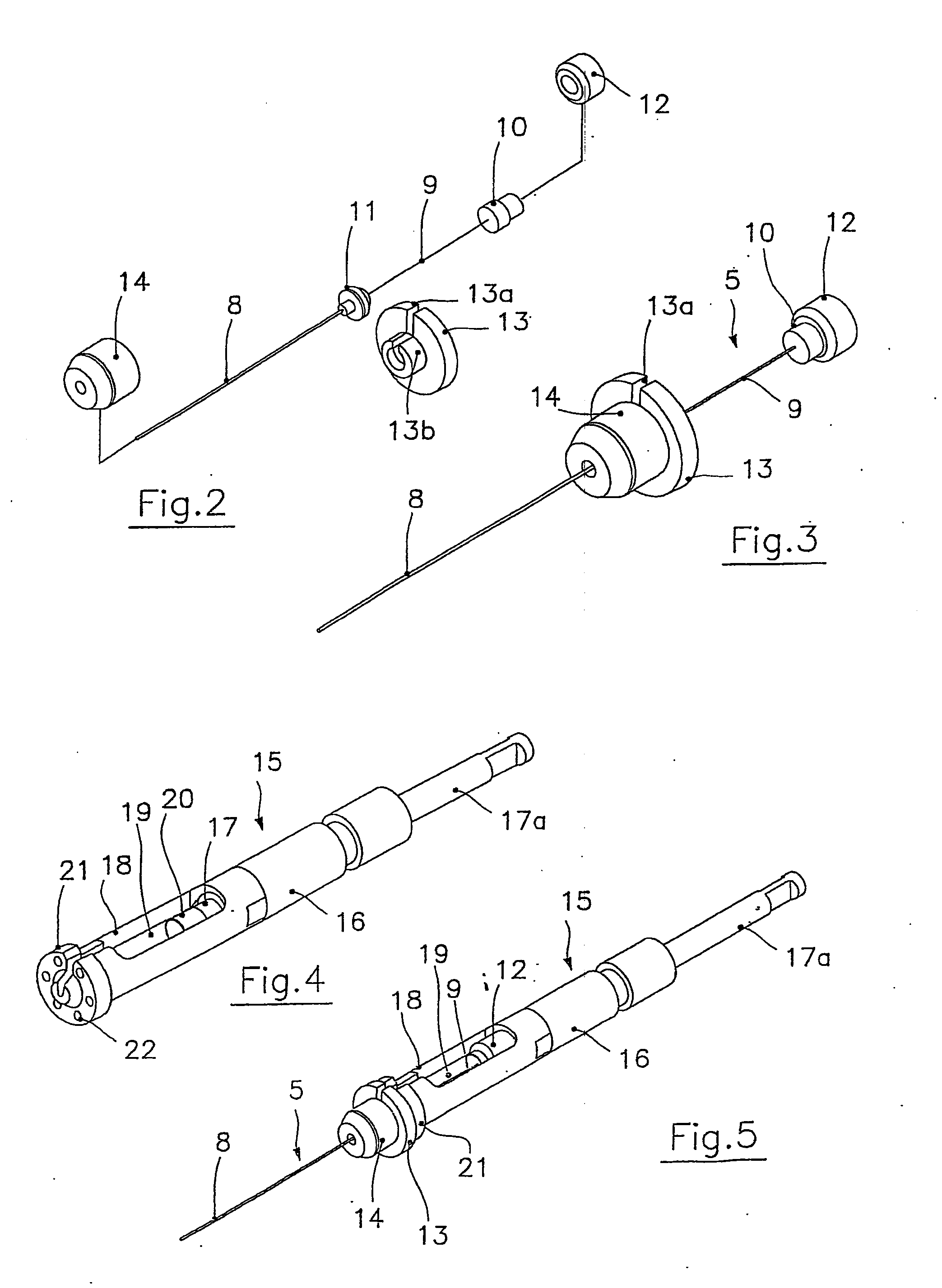
[0029]With reference to FIGS. 2 and 3, the sampling probe 5 according to the present invention comprises a conventional probe consisting of a needle 8, which slidingly houses an SPME fiber 9. A plastic ...


PUM

PropertyMeasurementUnit
magnetic forceaaaaaaaaaa
ferromagneticaaaaaaaaaa
chemical analysesaaaaaaaaaa

Abstract

An automatic solid-phase microextraction (SPME) sampling apparatus having a mobile sampler arm with a holder for a probe carrying a fiber 9 and an intermediate bracket for transferring the probe between a probe storage tray and the gas chromatograph injector. In the various probe handling stages, the probes are collected by a magnetic member attached to the end of the plunger in the holder, at the free end of the holder's body and at the lower end of the block for guiding the probe needle. The magnetic member interacts with a ferromagnetic connector attached to one end of the fiber and with a ferromagnetic flange attached to the end of the needle containing the fiber in order to place the probe on the transfer bracket or remove it therefrom. The apparatus can perform analyses on fibers that have already been exposed, extract analytes from samples, and subsequently transfer them for desorption in the gas chromatograph in a fully automatic way.

Description

FIELD OF THE INVENTION[0001]The present invention relates in general to the field of the instrumentation for chemical analyses, especially those carried out through gas chromatographic apparatuses. In particular, the invention concerns an automatic solid phase microextraction (SPME) sampling apparatus.DESCRIPTION OF THE PRIOR ART[0002]As is known, solid phase microextraction (SPME) is an analytical method that uses a fused silicon fiber on which a fluid polymer phase or a solid adsorbent, or a combination of the two, has been immobilized. The coated fiber (hereinafter called the SPME fiber) is immersed in a liquid sample, or in the headspace above the sample, to absorb the analytes of interest, which are subsequently desorbed with the aid of heat in the gas chromatograph injector and thus transferred to the capillary column. The method's selectivity can be varied by changing the type of phase coating the fiber, or its thickness. This analytical method has become widespread in variou...

Claims


Application Information

Patent Timeline
Patent Type & Authority Applications(United States)
IPC IPC(8): G01N30/00
CPCG01N1/405G01N30/24G01N2035/1053G01N2030/009G01N2030/062G01N35/1081
Inventor DEGLI ESPOSTI, FILIPPODUGHERI, VITTORIO
Owner DEGLI ESPOSTI FILIPPO
Why Eureka
Try Eureka