[0009]Briefly stated, the present invention is directed to a fire suppression
system comprising a plumbing
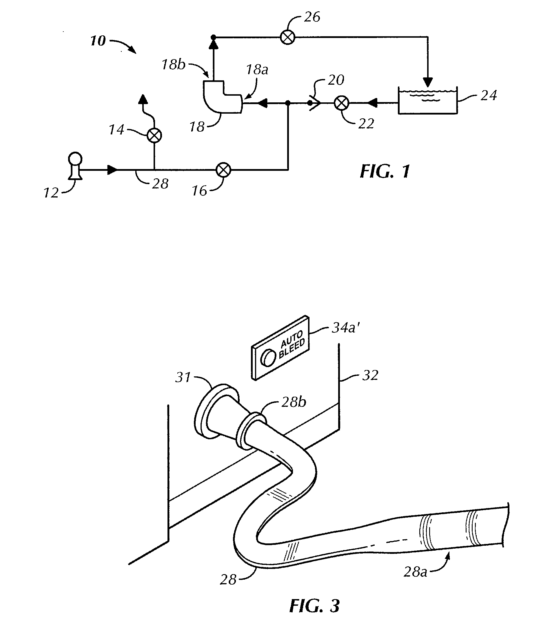
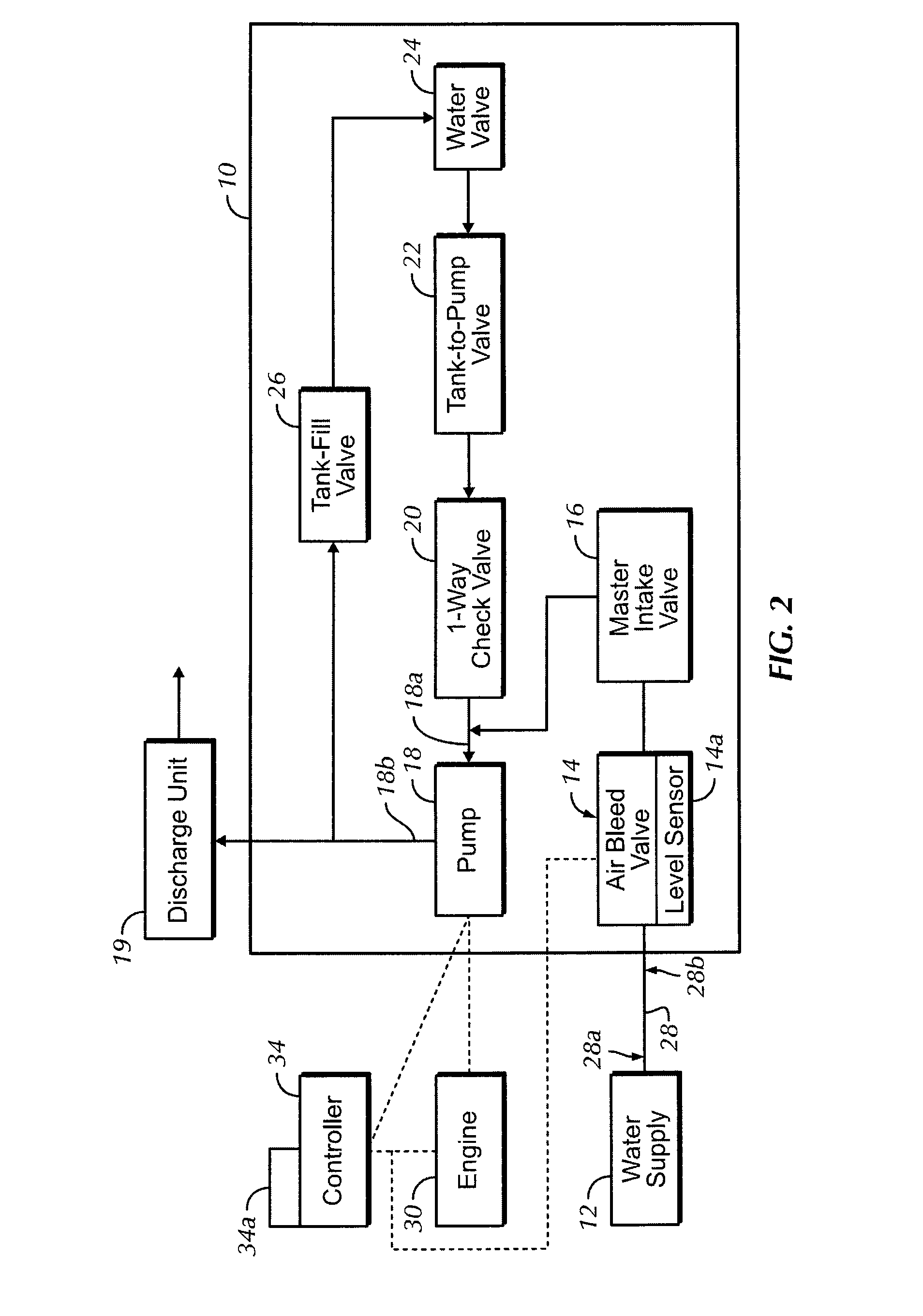
assembly, an engine, a hose, an air-bleed valve, and a controller. The plumbing
assembly includes a water tank, a pump having an input and an output in fluid communication with the water tank, a master intake valve in fluid communication with the input of the pump, and a one-way
check valve in fluid communication with the water tank, the pump, and the master intake valve. The one-way
check valve is located between the water tank and both the pump and the master intake valve. The engine drives the pump. The hose includes a second end, and a first end for connecting to a
water supply. The air-bleed valve is in fluid communication with the hose and the master intake valve and positioned between the second end of the hose and the master intake valve. The air-bleed valve includes a
level sensor for detecting the presence of air within the hose. The controller is operatively connected to the air-bleed valve, the engine, and the pump. The controller includes a one-touch activation control to activate the controller. The controller is configured to activate the air-bleed valve to remove air from the hose and to prevent increases in
pump pressure by the pump by preventing the engine from increasing engine speed when the controller receives a
signal from the air-bleed valve indicating the presence of air within the hose.
[0010]In another aspect, the present invention is related to a method of bleeding air from a hose for a fire suppression
system. The fire suppression system includes a plumbing assembly and an engine. The plumbing assembly includes a water tank, a tank-to-pump valve in fluid communication with the water tank, a pump in fluid communication with the tank-to-pump valve and the water tank, a master intake valve in fluid communication with the pump, and an air-bleed valve in fluid communication with the master intake valve. The air-bleed valve includes a
level sensor. A hose is connected to and in fluid communication with the air-bleed valve and a
water supply. The engine drives the pump. The method includes the steps of providing a controller that includes a one-touch activation control to activate the controller, wherein the controller is operatively connected to the air-bleed valve, the engine, and the master intake valve; actuating the one-touch activation control to activate the controller; sensing the presence of air within the hose by the
level sensor; signaling the controller of the presence of air sensed within the hose by the level sensor; outputting a command
signal from the controller to open the air-bleed valve to
bleed air upon receiving the
signal sensing the presence of air within the hose; and outputting a command signal from the controller to the engine to halt increases in engine speed to prevent increases in
pump pressure upon receiving the signal sensing the presence of air within the hose.
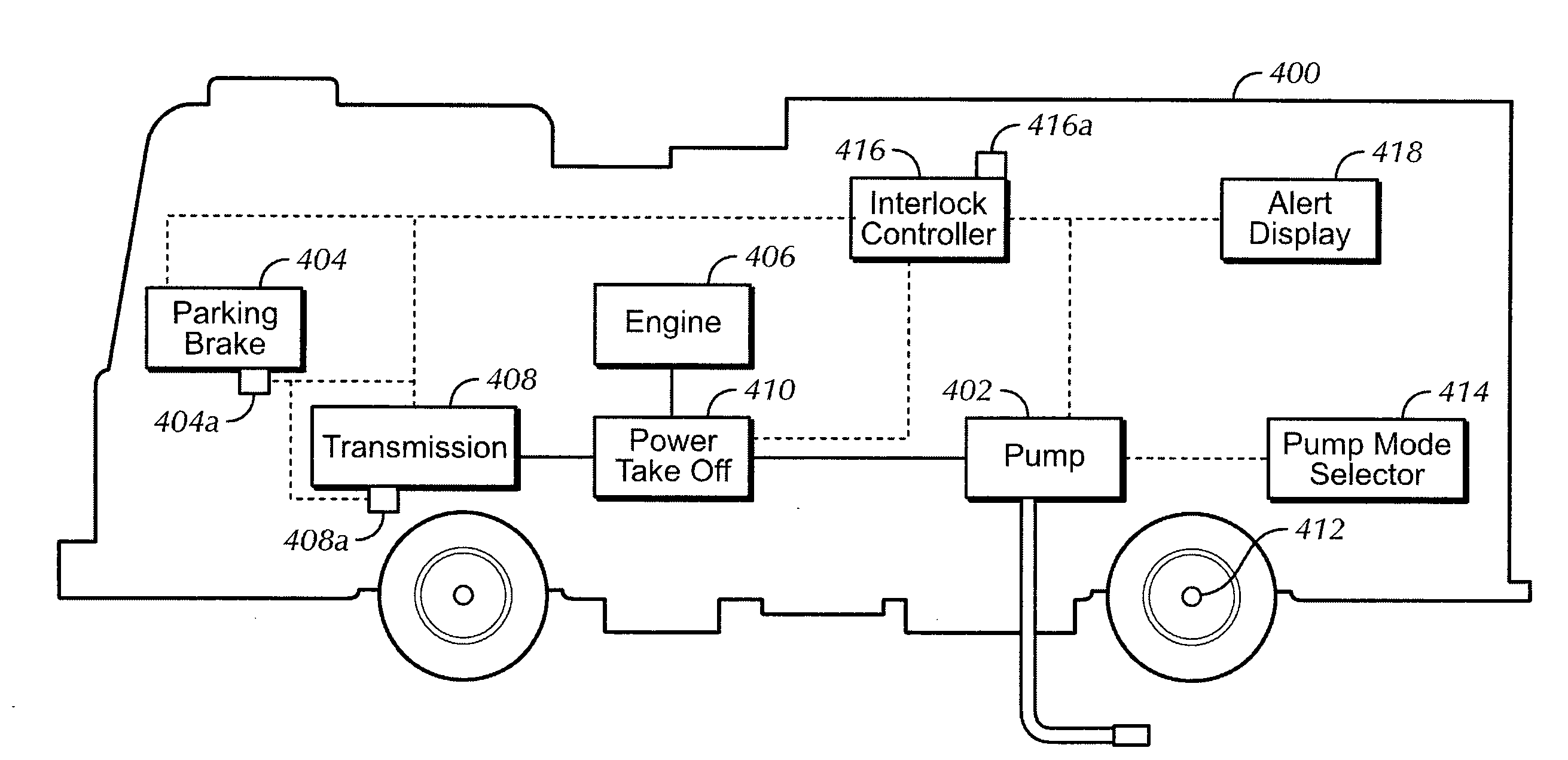
[0015]In yet another aspect, the present invention is directed to a method of operating an
interlock and pump shift for a fire truck. The fire truck includes a tank for holding a fire suppression fluid, a pump having at least one pump mode for pumping the fire suppression fluid, a plumbing assembly operatively connected to the pump, the tank, and the fire truck, the plumbing assembly having a tank-to-pump valve and a tank fill valve, a foam system connected to the plumbing assembly, a
parking brake for maintaining the fire truck in park, an engine having a low gear and a high gear for driving the fire truck, a
torque converter operatively connected to the engine, a transmission operatively connected to the
torque converter, a
drive shaft operatively connected to the transmission, a
power take off system operatively connected to the transmission for diverting
engine power from a drive axle of the fire truck to the pump, and an alert display for communicating one or more alerts. The method includes the steps of receiving an input of a selected pump mode; determining if the fire truck is moving when the input is received; outputting an alert signal to the alert display when the fire truck is moving; determining if the
parking brake is engaged when the fire truck is determined to be stationary; outputting an alert signal to the alert display when the
parking brake is disengaged; determining if the transmission is in neutral when the parking
brake is engaged; shifting the transmission into neutral when the parking
brake is disengaged if the transmission is not in neutral; shifting
engine power from the fire truck to the pump when the transmission is in neutral so as to enable operation of the selected pump mode; verifying that the shift of
engine power has been completed; increasing engine speed when the shift of engine power has been verified; driving the engine in the low gear after increasing engine speed; sensing the
drive shaft to determine if rotation of the
drive shaft has begun; shifting the transmission to the
neutral position when the drive shaft is stationary if the transmission is not in neutral; and driving the engine in the high gear when the drive shaft has been sensed to be rotating.

