Magnetic field forming device for active water and fluid treatment apparatus using the same

Active Publication Date: 2009-10-22
TOKO KABUSHIKI KAISHA
View PDF13 Cites 4 Cited by
  • Summary
  • Abstract
  • Description
  • Claims
  • Application Information

AI Technical Summary

Benefits of technology

[0037]As described above, according to the magnetic field forming device for active water and the fluid treatment apparatus using the same, the following effects may be brought about.
[0038]According to the first aspect of the invention,
[0039]According to the second aspect of the invention, in

Problems solved by technology

However, there are the following problems in the prior art.
Therefore, it is necessary that the magnets are disposed with predetermined orientations when assembling the apparatus, wherein it becomes cumbersome to assemble the apparatus while checking the orientation of the magnets, and since the polarity of the magnets are not visible, there is a possibility for a worker to assemble the apparatus with a difference in the orientation of the magnets.
As such, there is a problem in that since water flowing between magnets opposed to each other with the same polarity is not activated, an apparatus whose activ

Method used


Image

  • Magnetic field forming device for active water and fluid treatment apparatus using the same
  • Magnetic field forming device for active water and fluid treatment apparatus using the same
  • Magnetic field forming device for active water and fluid treatment apparatus using the same

Examples


Example

Embodiment 1

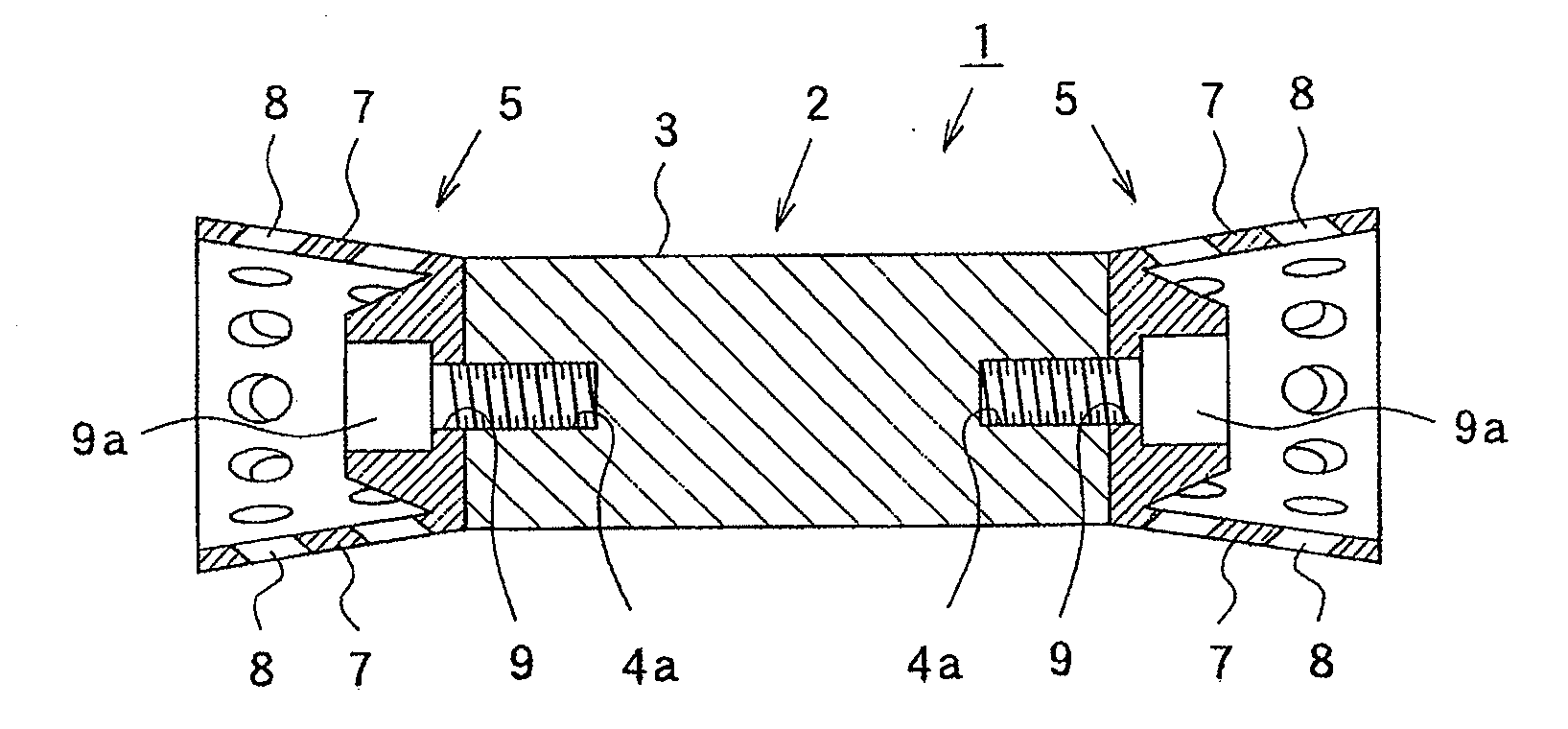
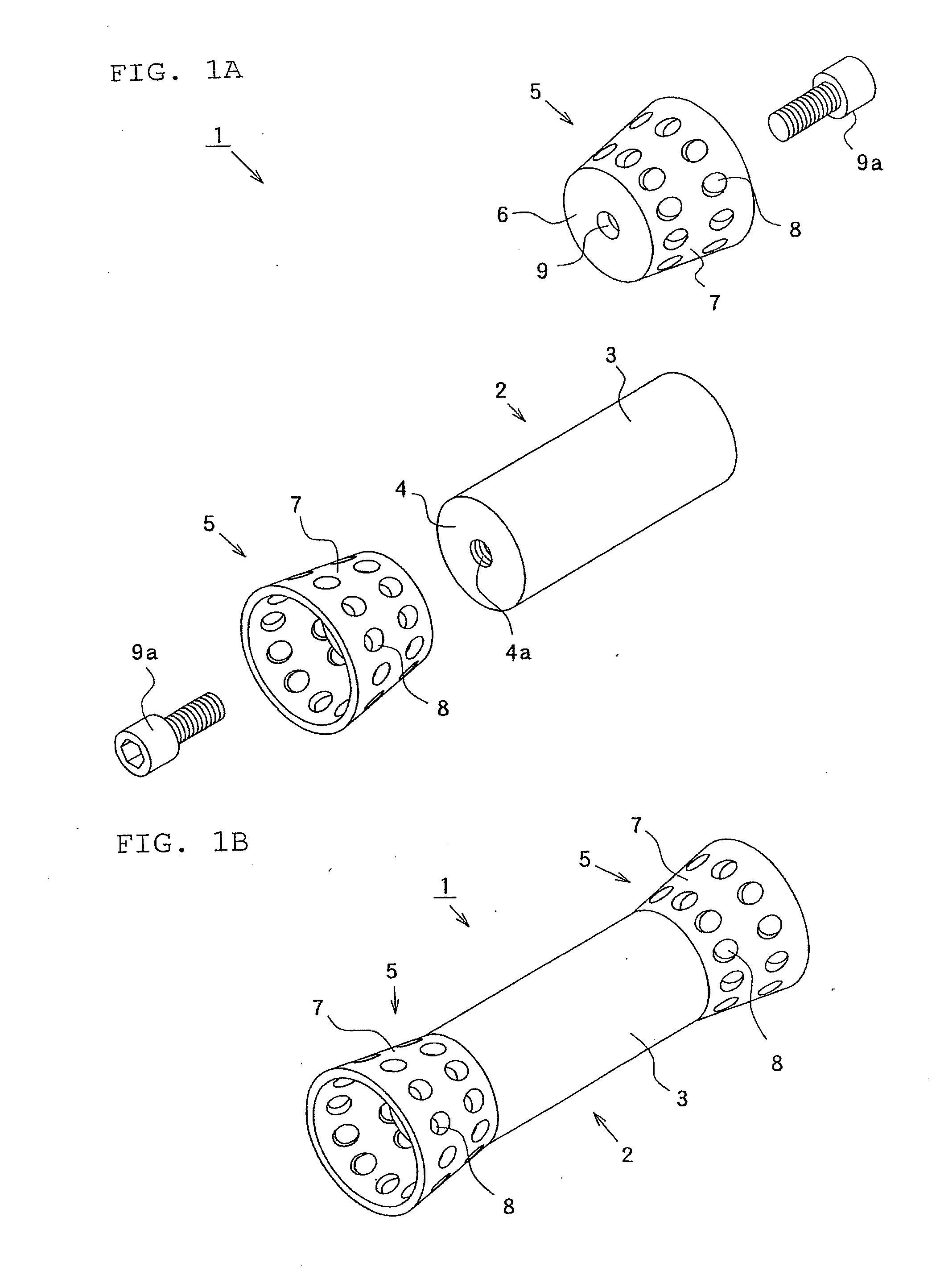
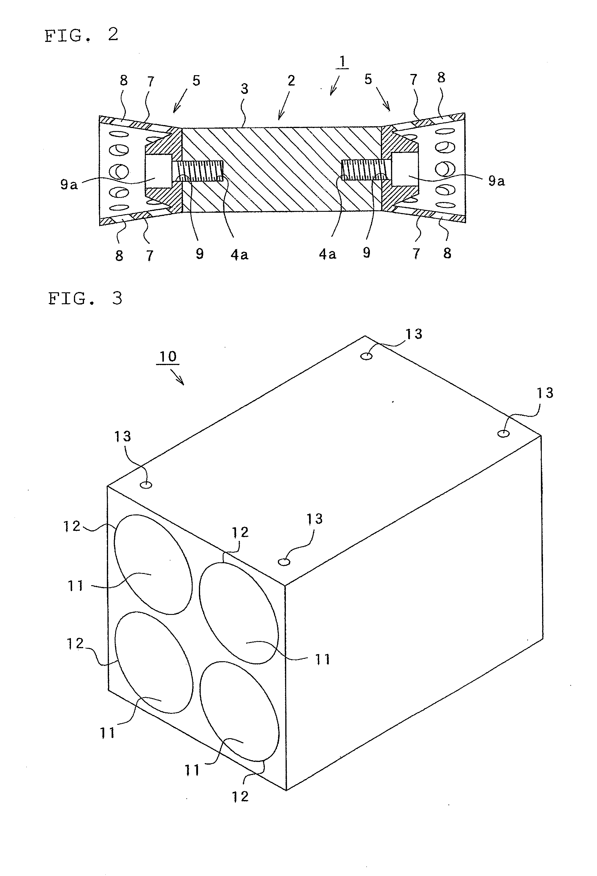
[0105]FIG. 1A is a disassembled perspective view showing a magnetic field forming device for active water according to Embodiment 1 of the present invention, FIG. 1B is a perspective view showing the magnetic field forming device for active water, and FIG. 2 is a sectional view showing the major parts of the magnetic field forming device for active water.

[0106]In FIG. 1 and FIG. 2, reference numeral 1 denotes a magnetic field forming device for active water according to Embodiment 1 of the present invention, 2 denotes a magnet formed of rare earth Cobalt magnet etc., formed to be like a round bar, 3 denotes the side of the magnet 2, 4 denotes an end side of the magnet 2, 4a denotes a threaded hole portion formed at the end side 4 of the magnet 2, 5 denotes a guide member that is formed of a non-magnetic material such as aluminum alloy, copper alloy, titanium alloy, Inconel, stainless steel, high manganese steel, synthetic resin, and inorganic material, etc., and is adher...

Example

Embodiment 2

[0125]FIG. 8 is a perspective view showing a magnetic field forming device for active water according to Embodiment 2, FIG. 9A is a perspective view observed from the inclined portion side of a guide member of a magnetic field forming device for active water according to a modified version of Embodiment 2, and FIG. 9B is a perspective view observed from the base portion side. Also, parts that are similar to those described in Embodiment 1 are given the same reference numerals, and the description thereof is omitted.

[0126]In FIG. 8, reference numeral 1a denotes a magnetic field forming device for active water according to Embodiment 2 of the present invention, 2 denotes a magnet, 3 denotes the side of the magnet 2, 5a denotes a guide member formed of a non-magnetic material such as aluminum alloy, copper alloy, titanium alloy, Inconel, stainless steel, high manganese steel, synthetic resin, inorganic material, etc., 6a denotes a base portion formed to be cylindrical, the ...

Example

Embodiment 3

[0130]FIG. 10 is a sectional view showing the major parts of a fluid treatment apparatus according to Embodiment 3 of the present invention, and FIG. 11 is a sectional view showing the major parts of a fluid treatment apparatus according to a modified version of Embodiment 3. Also, parts that are similar to those described in Embodiment 1 are given the same reference numerals, and the description thereof is omitted.

[0131]In FIG. 10, reference numeral 41 denotes a fluid treatment apparatus according to Embodiment 3, 42 denotes a treatment chamber of the fluid treatment apparatus 41, which is formed of a light material almost free from corrosion such as titanium alloy, Inconel, stainless steel, high manganese steel, synthetic resin, inorganic material, etc., to be like a rectangular parallelepiped box having a bottom with its upper surface open, and in which casings 10 having four magnets 2 accommodated at the bottom thereof are juxtaposed by two lines, 43 denotes a casing...


PUM

PropertyMeasurementUnit
Polarityaaaaaaaaaa
Diameteraaaaaaaaaa
Magnetic fieldaaaaaaaaaa

Abstract

An object of the present invention is to provide a magnetic field forming device for active water capable of uniformly forming a high magnetic field free from any unevenness in its intensity, activating a fluid regardless of the orientation of magnetic polarity of the magnets, bringing about excellent assembling efficiency not requiring assembling while checking the orientation of the magnets, being manufactured at a high product yield ratio without occurrence of defective products resulting from a difference in the orientation of the magnets, remarkably easily taking out the magnets without use of any exclusive special tool, and removing rust and stains adhered to the magnets by wiping off the magnets one by one, the maintenance efficiency of which is excellent. The magnetic field forming device for active water in which a flow path of a fluid is formed in a through hole, and the same magnetic field forming device includes a rod-shaped magnet 2 disposed with predetermined spacing from the inner wall of the through hole and having a fluid flow path formed between the inner wall and the side 3; a guide member 5 adhered to and fixed to the end part of the magnet 2, which is inserted into the interior of the through hole; and a communication portion 8 formed at the guide member 5, which communicates with the fluid flow path.

Description

CROSS REFERENCE TO RELATED APPLICATION[0001]This application is a National Stage of International Application No. PCT / JP2008 / 050500 filed Jan. 17, 2008, claiming priority based on Japanese Patent Application No. 2007-120164, filed Apr. 27, 2007, the contents of all of which are incorporated herein by reference in their entirety.TECHNICAL FIELD[0002]The present invention relates to a magnetic field forming device for active water, which activates a fluid by causing the fluid to pass through a magnetic field, and fluid treatment apparatus using the same.BACKGROUND OF THE INVENTION[0003]A fluid treatment apparatus has conventionally been known, which magnetically treats a fluid flowing in a piping by disposing a rod-shaped permanent magnet in the piping.[0004]As a prior art in such a fluid treatment apparatus, Patent Document 1 discloses “a water activating apparatus that magnetically treats and activates water flowing between the sides of opposed magnets (water flowing channel) by dis...

Claims


Application Information

Patent Timeline
IPC IPC(8): C02F1/48
CPCC02F1/006C02F2303/14C02F1/481C02F1/48C02F2201/48
Inventor YAMASAKI, JUNICHI
Owner TOKO KABUSHIKI KAISHA
Why Eureka
Try Eureka