Compact superconducting magnet configuration with active shielding having a shielding coil contributing to field formation

a superconducting magnet and active shielding technology, applied in the direction of superconducting magnets/coils, using reradiation, electric/magnetic detection for well-logging, etc., can solve the problems of general undesired, magnetic field, failure of pacemakers, etc., to facilitate alignment and charging of the magnet configuration and strong homogenizing

Active Publication Date: 2009-10-22
BRUKER BIOSPIN
View PDF8 Cites 16 Cited by
  • Summary
  • Abstract
  • Description
  • Claims
  • Application Information

AI Technical Summary

Benefits of technology

[0033]Alternatively, it is also possible in accordance with the invention to deviate from this particularly simple embodiment and envision structured solenoid coils as shielding coils. It can be envisioned, for example, that the shielding coil of a magnet configuration in accordance with the invention consists of two unstructured solenoid coils located mirror-symmetrically with respect to the center of the examination volume, wherein Lsep<0.15*Labs obtains for the axial separation Lsep between these solenoid coils. It should be noted that the two unstructured solenoid coils can also be understood as two separate windings of one structured solenoid coil. In this embodiment, the shielding coil is two-part. In particular, shielding coils which are very short axially can help avoid an excessively sharp drop in the static magnetic field at the center of the examination volume.
[0034]In another preferred embodiment, Lmax>0.5*Rif obtains for the axial distance Lmax of the maxima of the field strength of the magnetic profile generated by the main field coil and the shielding coil and for the inner radius Rif of the field formation device. This dimensioning enables a particularly wide, homogeneous static magnetic field.
[0035]In a preferred embodiment of the magnet configuration in accordance with the invention, the field strength Bmax of the maxima of the magnetic field profile generated by the main field coil and the shielding coil is between 10 ppm and 10,000 ppm, preferably between 100 ppm and 5000 ppm, stronger than the field strength Bmin of the central minimum of this magnetic field profile. These relative values of the maxima result in a particularly strong homogenizing effect of the overlapping of the magnetic field profiles of the main and shielding coils and of the ferromagnetic field formation device.
[0036]In another preferred embodiment, the main field coil and the shielding coil are connected in series. The same current therefore flows through the main field coil and the shielding coil. This facilitates alignment and charging of the magnet configuration.
[0037]A preferred further embodiment provides a superconducting switch for shortcircuiting the circuit formed by the main field coil and the shielding coil. This enables the magnet configuration to be operated in “persistent mode” (continuous operation without a power supply).

Problems solved by technology

This external magnetic field is also referred to as the “stray field” and is generally undesired as it may interfere with technical devices in the environment.
For example, stray fields can delete magnetic memories from hard disks or credit cards or cause failure of pacemakers.
An essential disadvantage of such magnet configurations with structured main field coils consists in this very high surface pressure which causes mechanical relaxation processes in the adjacent windings of superconductor wire, which can then pass into their normal conducting state as a result of their vanishing heat capacity at their low working temperature to thereby cause a so-called quench.
Such an event is undesirable and expensive, since, during a quench, the temperature of the magnet coil rises from the working temperature to values in the 40 to 80 K region, the expensive liquid helium used for cooling evaporates and is lost, and re-starting the magnet configuration can cause delays of several days.
Magnet configurations with a larger usable diameter of 30 cm and more, for instance, are not possible with this limitation.
However, in magnet configurations with a usable diameter of 60 cm and more, for instance, the magnet body, and thus the entire magnet configuration, becomes very heavy, thereby rendering transport expensive and limiting the options for setting up the magnet configuration due to great floor loading.

Method used


Image

  • Compact superconducting magnet configuration with active shielding having a shielding coil contributing to field formation
  • Compact superconducting magnet configuration with active shielding having a shielding coil contributing to field formation
  • Compact superconducting magnet configuration with active shielding having a shielding coil contributing to field formation

Examples


Embodiment Construction

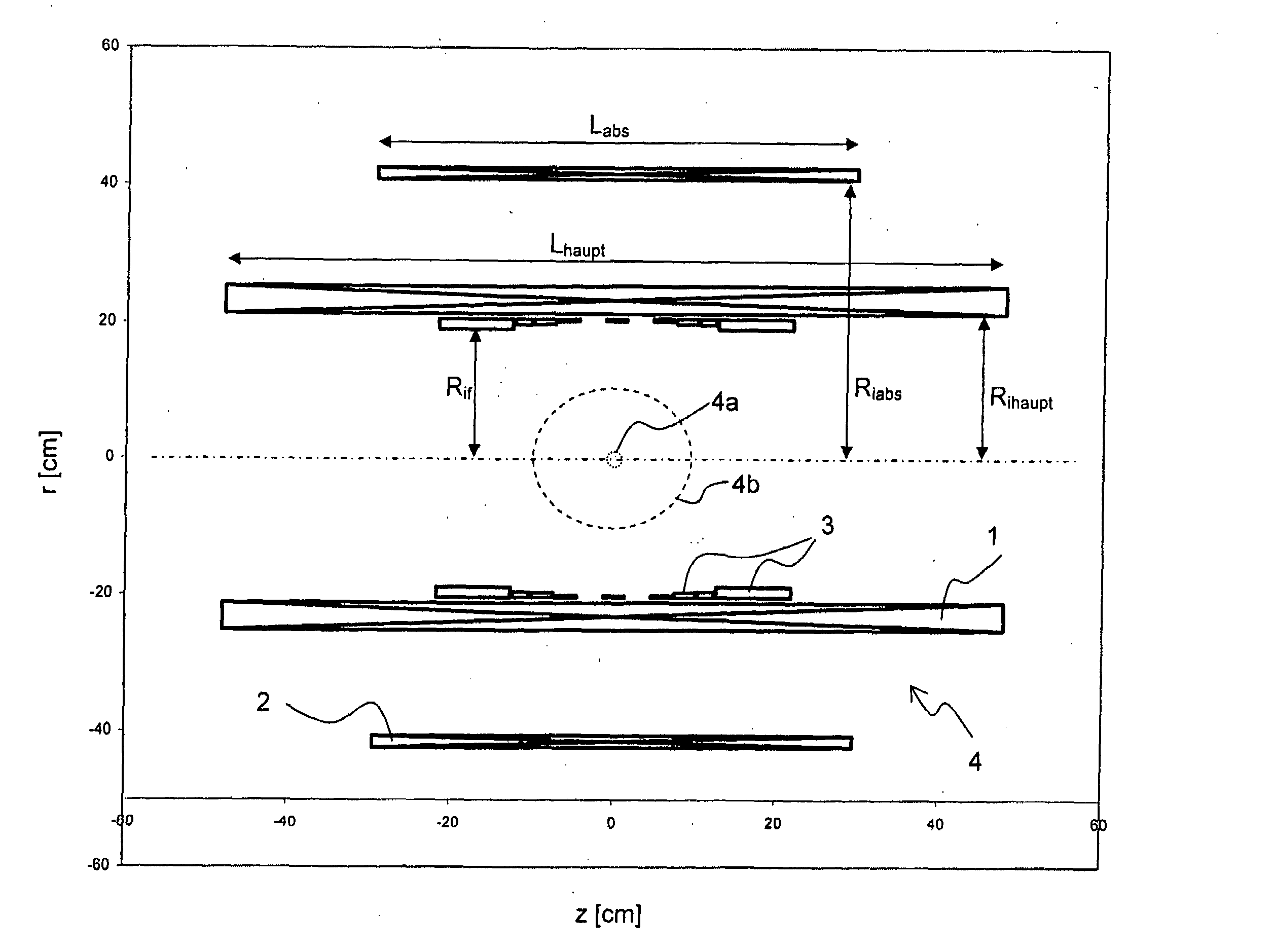
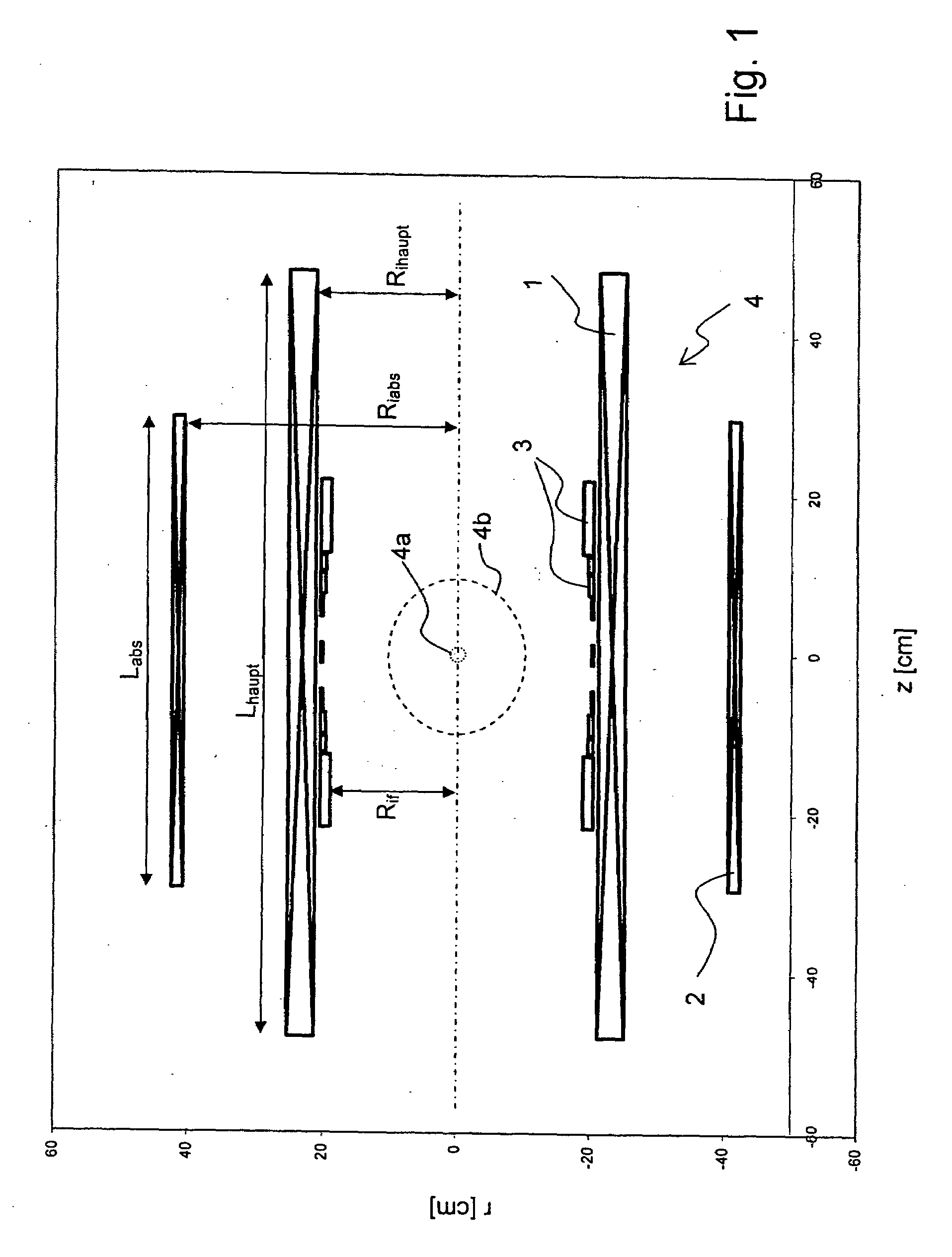
[0057]FIG. 1 illustrates a first embodiment of a magnet configuration in accordance with the invention, showing a true-to-scale, schematic, cross-sectional view. The magnet configuration 4 consists of a main field coil 1, a shielding coil 2, and a ferromagnetic field formation device 3. No further means for generating the magnetic field are used. The magnet configuration 4 is essentially rotational symmetric about the axis running in the z-direction (indicated by the dot-dashed line).

[0058]The magnet configuration 4 generates a homogeneous magnetic field B0 in an examination volume 4b around its center 4a (at z=0, r=0) which is aligned along the z-axis and has a strength of 7.055 T in the center 4a.

[0059]The main field coil 1 is an unstructured solenoid coil having an inner radius Rihaupt of 0.216 m, an exterior diameter of 0.253 m and a length Lhaupt of 0.96 m. The mean current density of this coil is 11.92746 A / m2. The shielding coil 2 is also an unstructured solenoid coil with a...


PUM

PropertyMeasurementUnit
temperatureaaaaaaaaaa
radial distanceaaaaaaaaaa
diameteraaaaaaaaaa

Abstract

A superconducting magnet configuration (4; 14) for generating a homogeneous magnetic field B0 in an examination volume (4b), has an interior radial superconducting main field coil (1) which is disposed rotationally symmetrically about an axis (z-axis) and an oppositely driven coaxial radially exterior superconducting shielding coil (2) is characterized in that the magnet configuration (4; 14) consists of the main field coil (1), the shielding coil (2), and a ferromagnetic field formation device (3; 18), wherein the ferromagnetic field formation device (3; 18) is located at the radially inside of the main field coil (1), the main field coil (1) consisting of an unstructured solenoid coil or of several radially nested unstructured solenoid coils (15, 16) which are driven in the same direction, the axial extent Labs of the shielding coil (2) being smaller than the axial extent Lhaupt of the main field coil (1), wherein the axial magnetic field profile (5) generated by the main field coil (1) and the shielding coil (2) during operation has a minimum of the field strength along the axis (z-axis) in the center (4a) and a maximum of the field strength on each side of the center (4a), and wherein the axial magnetic field profile (6) generated by the ferromagnetic field formation device (3; 18) during operation has a maximum of the field strength along the axis (z-axis) in the center (4a) and a minimum of the field strength on each side of the center (4a). The magnet configuration in accordance with the invention has a very simple structure.

Description

[0001]This application claims Paris Convention priority of DE 10 2008 020 107.3 filed Apr. 22, 2008 the complete disclosure of which is hereby incorporated by reference.BACKGROUND OF THE INVENTION[0002]The invention concerns a superconducting magnet configuration with active shielding for generating a homogeneous magnetic field B0 in an examination volume,[0003]having an radially inner superconducting main field coil which is disposed rotationally symmetrically about an axis (z-axis)[0004]and a coaxial radially exterior superconducting shielding coil which is operated in an opposite manner.[0005]Such a magnet configuration is known, for example, from EP 1 564 562 A1.[0006]Nuclear Magnetic Resonance (NMR) is a method for examining the characteristics of a sample. NMR spectroscopy is used for analyzing the chemical composition (or rather the chemical bonds) of a sample. NMR tomography is used, as a rule, for determining the proton density (or rather the water content) as a function of...

Claims


Application Information

Patent Timeline
Patent Type & Authority Applications(United States)
IPC IPC(8): B01D59/44H01F6/00G01V3/32G01V3/08
CPCG01R33/3815G01R33/3873H01F27/38H01F6/06H01F27/365G01R33/421H01F27/36H01J49/38
Inventor NEUBERTH, GERALDWESTPHAL, MICHAEL
Owner BRUKER BIOSPIN
Why Eureka
Try Eureka