
Method for Manufacturing an Inner Liner For a Storage Tank

a storage tank and inner liner technology, applied in the direction of mechanical equipment, vessel construction details, electrochemical generators, etc., can solve the problems of no production vehicle fueled by compressed hydrogen, no standard that addresses the environmental concerns of compressed gas permeation, and likely to be much more restrictive than the current emissions standard, etc., to achieve strong mechanical connection, strong and impermeable connection, and limit the risk of permeability

Active Publication Date: 2009-10-22
PLASTIC OMNIUM NEW ENERGIES FRANCE
View PDF21 Cites 18 Cited by
  • Summary
  • Abstract
  • Description
  • Claims
  • Application Information

AI Technical Summary

Benefits of technology

[0017]According to one aspect of the invention, a peripheral end portion of the end cap is provided with a peripheral connection tab for welding to a peripheral connection tab of the open end of the cylindrical body. Such a connection allows limiting the risk of permeability at the connection between the end cap and the cylindrical body and provides a strong mechanical connection.
[0018]By “connection tab” is meant an extension of the wall of the cylindrical body and the end cap respectively that allows both parts to be welded to each other on a substantial portion of one of their outer surfaces. Preferably, these tabs are bended inwards so that the external surfaces of both parts are welded together, giving a projection inwards which, through its configuration, gives a strong and impermeable connection.
[0019]The dimensions of the welding tab are preferably greater than the wall thickness of the outer shell, as to facilitate the fold over of the material, but sufficiently small enough to ensure that the mechanical properties of the weld are not significantly different than those of the rest of the liner, hereby mitigating the risk of failure due to a stress riser. Welding tabs with a length of at least twice the wall thickness, but not more than 5 or even 4 times the wall thickness of the liner, are a good compromise in that regard.
[0020]With such a method, an inner liner with good emission results can be more cost-effectively produced. It is not necessary to use a complex injection molding process to produce the entire inner liner. The conventional blow molding technique, which is well known in the field of regular fuel tanks, can be used for making the cylindrical body. Also, the present method provides an easy and effective solution for manufacturing inner liners of different lengths. Indeed, a dome-shaped end cap can be connected to a cylindrical body of any length to form the completed inner liner. Furthermore, the inner liner according to the present method provides excellent permeation qualities and is suitable in connection with storage tanks for compressed hydrogen. Finally, the end caps may for instance be made by over molding the accessories required for the tank function(s) or by thermoforming existing parts and fixing said accessories (or connecting parts therefore) on these thermoformed parts.
[0021]In the method according to the invention, the end cap is preferably also provided with at least one structural layer and at least one barrier layer. In both parts (cylindrical body and end cap), the barrier layer is preferably sandwiched between two structural layers, as it is the case in conventional fuel tanks. The presence of a barrier layer in the entire liner of the invention further increases its permeation performances. As a consequence, a storage tank with an inner liner as manufactured using this preferred embodiment can be used to reduce the emissions from the storage tanks into the atmosphere. It also allows the storage of gasses of smaller molecule size, as e.g. hydrogen.

Problems solved by technology

There is, however, currently no standard that addresses the environmental concerns of compressed gas permeation.
When such a standard is introduced, it is likely to be much more restrictive than the current emissions standard.
There are currently no production vehicles being fueled by compressed hydrogen.
For compressed hydrogen, these conventional tanks do however not necessarily meet the requirements, especially if, as expected, more restrictive requirements are introduced.
These tanks show excellent emission results but are rather expensive.
However, such a liner is a monolayer polypropylene one, which leads to bad results in terms of permeability.
However, the method of fabrication of the liner disclosed in that document is rather complicated because the liner is made in one piece by multiple step injection molding.
However, welding of multilayer structures generally lead to connection problems in the welding zone (namely in terms of mechanical performances and permeability).

Method used


Image

  • Method for Manufacturing an Inner Liner For a Storage Tank
  • Method for Manufacturing an Inner Liner For a Storage Tank
  • Method for Manufacturing an Inner Liner For a Storage Tank

Examples


Embodiment Construction

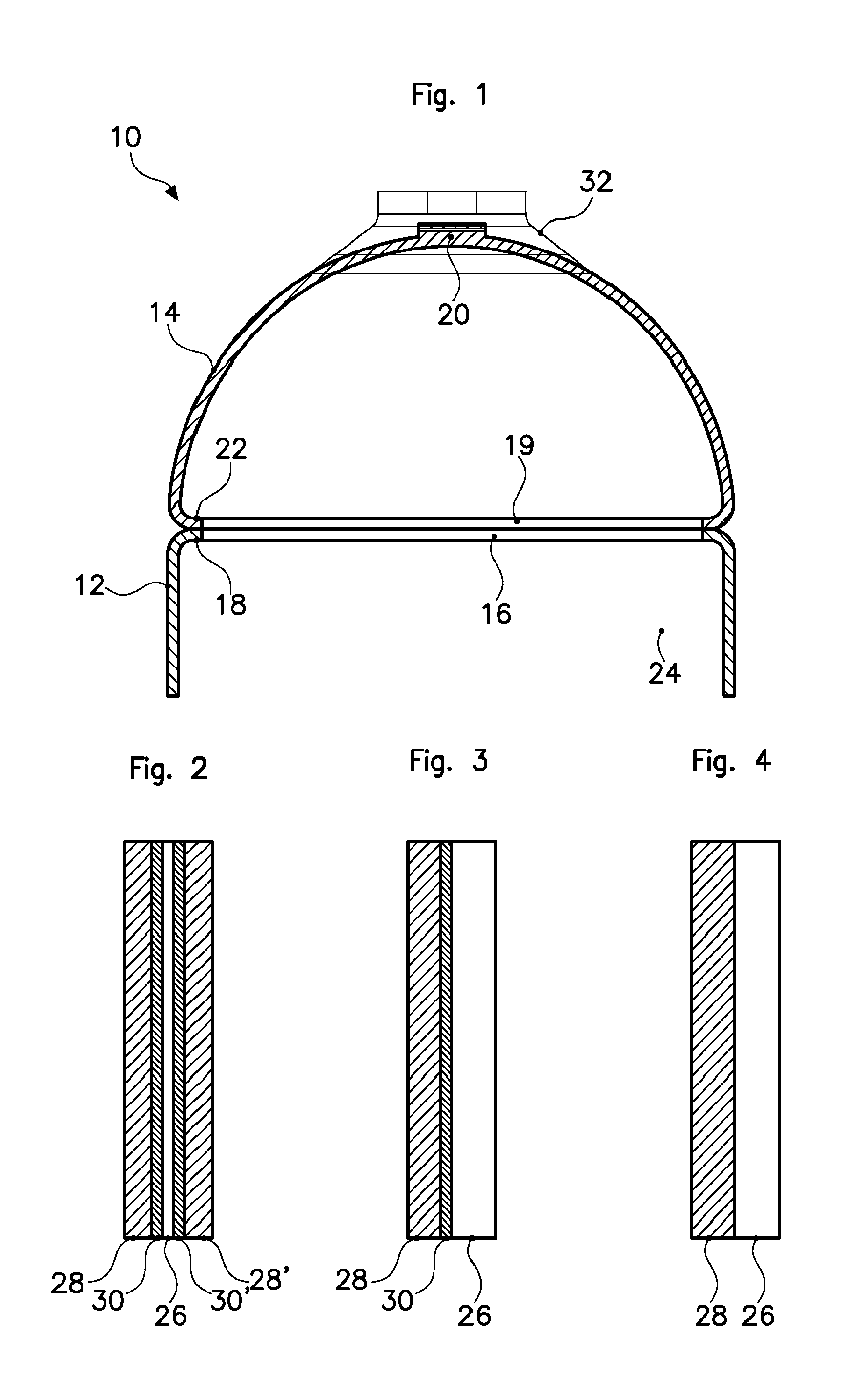
[0040]Referring to FIG. 1, a top section of a polymeric inner liner is indicated generally at 10 and comprises a cylindrical body 12, a first end of which is shown in FIG. 1, and a dome-shaped end cap 14.

[0041]The cylindrical body 12 comprises a first open end 16 and comprises a first peripheral connection tab 18.

[0042]The end cap 14 has a base and an apex, wherein the base has a second open end 19 and the apex has a communication opening 20 for forming a communication between the inner chamber of the storage tank and the exterior of the storage tank. The end cap 14 comprises, at its base, a second peripheral connection tab 22.

[0043]The peripheral connection tabs 18, 22 are arranged in such a way that, when the end cap 14 is placed on the first end of the cylindrical body 12, the peripheral connection tabs 18, 22 are in alignment and can be connected by welding. Once welded together, the cylindrical body 12 and the end cap 14 form an inner chamber 24 wherein compressed gas can be st...


PUM

PropertyMeasurementUnit
thicknessaaaaaaaaaa
thicknessaaaaaaaaaa
pressureaaaaaaaaaa

Abstract

A method for manufacturing a polymeric inner liner for a storage tank, particularly a hydrogen storage tank, comprising:providing a cylindrical body of polymer material, having a first open end and a first peripheral connection tab at the first open end, the cylindrical body comprising a structural layer and a barrier layer;providing a dome-shaped end cap of polymer material having a base with a cross-section essentially corresponding to a cross-section of the first open end of the cylindrical body and having a second peripheral connection tab at a peripheral end portion of such end cap;placing the end cap with its base onto the first open end of the cylindrical body and with the first and second peripheral tabs in contact with each other; andwelding both peripheral connection tabs together.A storage tank made using such liner. Use of such tank for storing hydrogen.

Description

[0001]This application claims priority to U.S. provisional application 60 / 786716 filed Mar. 29, 2006 and incorporated herein by reference.BACKGROUND OF THE INVENTION[0002]The present invention relates to a method for manufacturing a polymeric inner liner for a storage tank, in particular for a hydrogen storage tank.[0003]Compressed gas is becoming an increasingly popular choice for transportation fuels. As more and more vehicles use compressed gas as fuel, more emphasis needs to be put on the emissions of the fuel systems of such vehicles. Currently, there is a requirement from compressed gas fuel systems that addresses the safety risks of gas permeation from such a system. There is, however, currently no standard that addresses the environmental concerns of compressed gas permeation. When such a standard is introduced, it is likely to be much more restrictive than the current emissions standard.[0004]The vast majority of the compressed gas tanks used on transportation vehicles toda...

Claims


Application Information

Patent Timeline
Patent Type & Authority Applications(United States)
IPC IPC(8): B65H81/06B29C65/00B29C49/00B29C51/12C01B3/02
CPCF17C1/00Y02E60/321F17C2201/0104F17C2201/056F17C2203/0604F17C2203/0619F17C2203/0621F17C2203/0636F17C2203/066F17C2203/0663F17C2205/0305F17C2209/22F17C2209/221F17C2209/232F17C2221/012F17C2221/032F17C2223/0123F17C2223/035F17C2260/011F17C2260/012F17C2260/036F17C2270/0184F17C2270/0763F17C1/16Y02E60/32
Inventor MEHTA, SAURINHILL, DAVIDTHOMPSON, JAMES EDWARD
Owner PLASTIC OMNIUM NEW ENERGIES FRANCE
Learn More