

Multi-spectral, selectively reflective construct
a selective reflective and multi-spectral technology, applied in the direction of film/foil adhesives, nuclear elements, nuclear engineering, etc., can solve the problems that the effective multi-spectral solution of swir, mwir, lwir, nir, etc., cannot be found to control reflectance, transmission and absorption properties, and achieve the effect of low emissivity surfa
- Summary
- Abstract
- Description
- Claims
- Application Information
AI Technical Summary
Benefits of technology
Problems solved by technology
Method used
Image

Examples
example 1
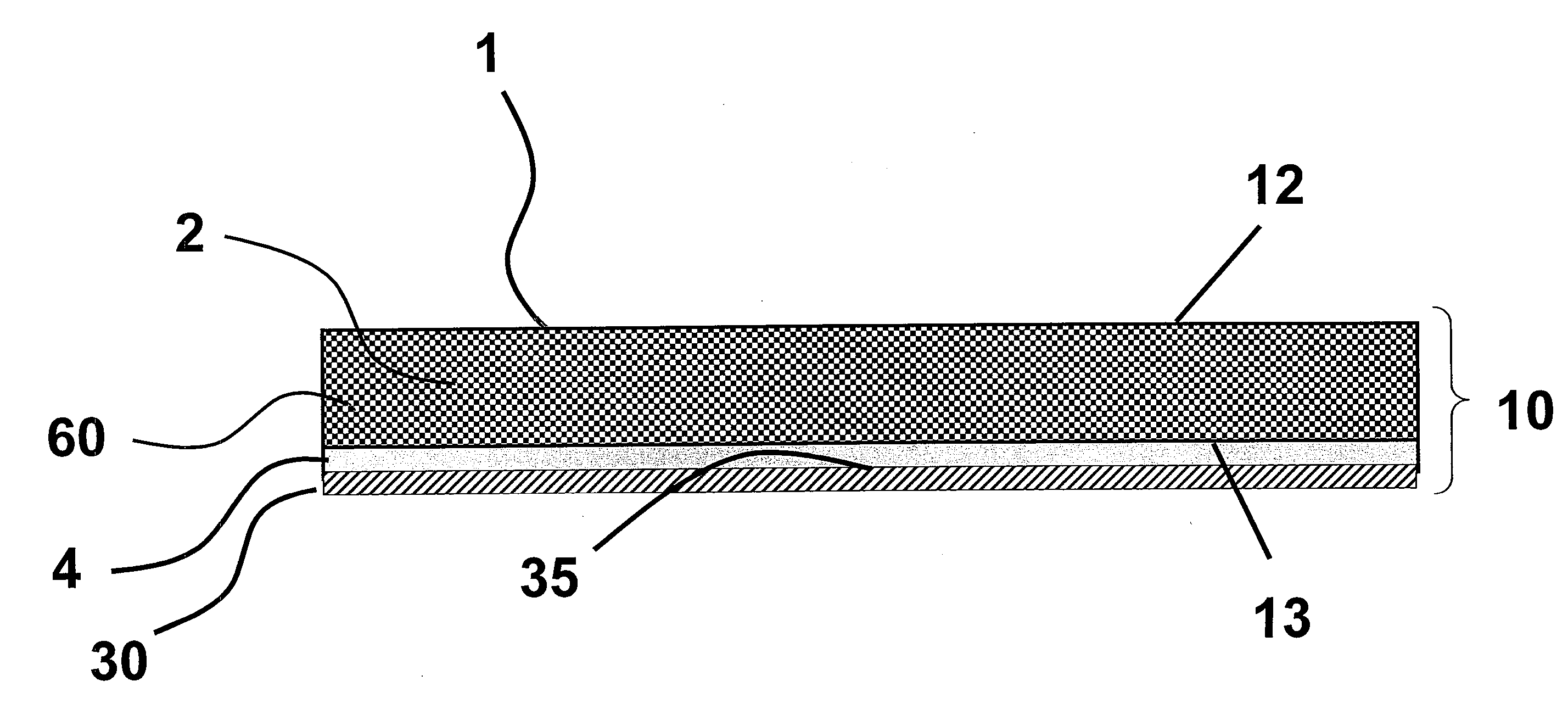
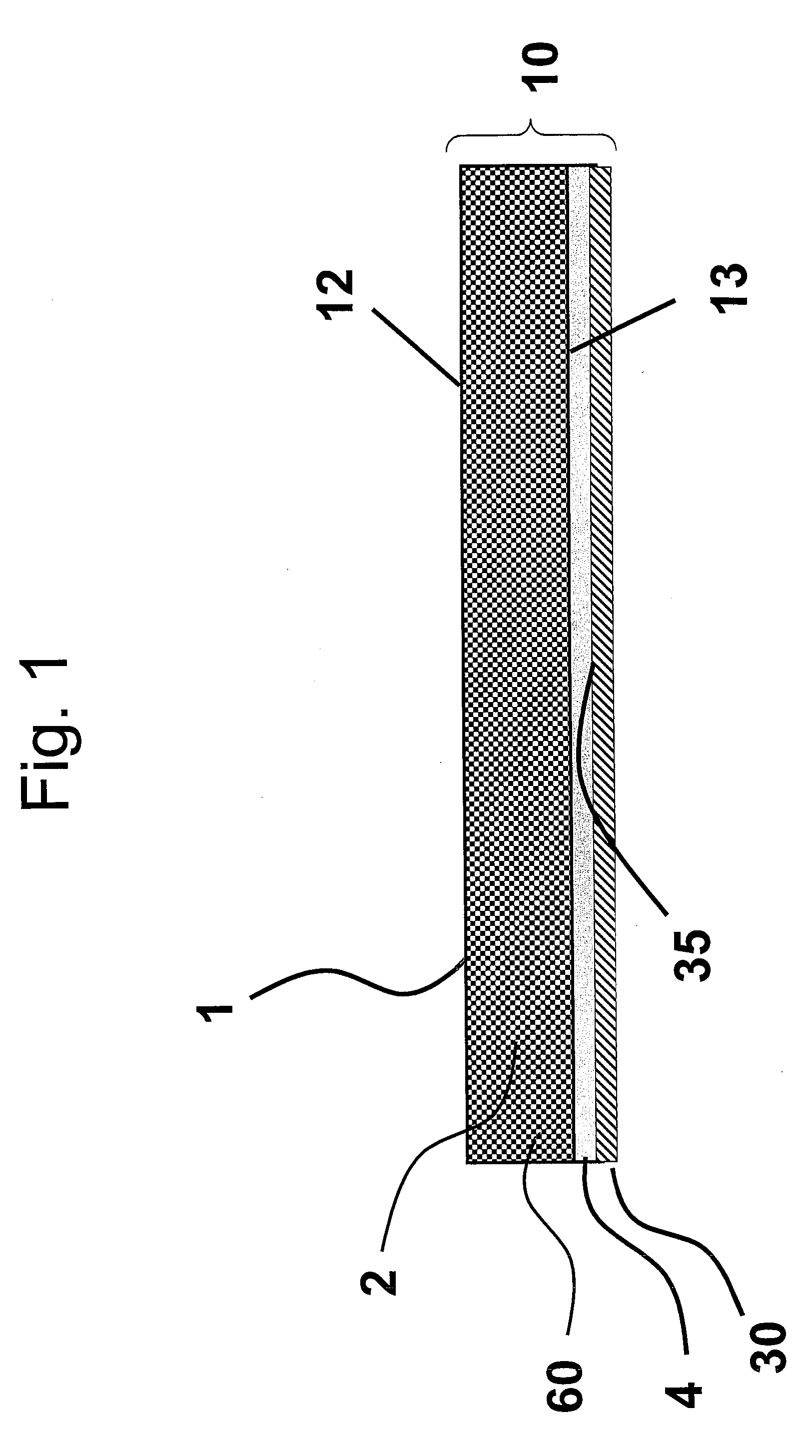
[0084]A sample of a construct was prepared comprising carbon-coated ePTFE and metallized ePTFE, in the following manner.
[0085]A first component comprising carbon-coated ePTFE representing the first substrate was prepared as described in Example 3 of U.S. Patent Application Publication No / 2007 / 0009679 with the following exceptions. The ePTFE membrane used had a thickness of about 30 μm, a weight of about 9 grams per square meter, and an average pore size of about 0.2 μm. The amount of carbon black used was about 0.9% by weight of ePTFE membrane. Optical density and thermal reflection properties of the first substrate of the first component were measured according to the test methods herein, and reported in Table 1.
[0086]A second component comprising metallized ePTFE was prepared in accordance with U.S. Pat. No. 5,955,175, representing the thermally reflective layer. Emissivity was measured on the metallized side according to the test methods herein, and reported in Table 1.
[0087]The...
example 2
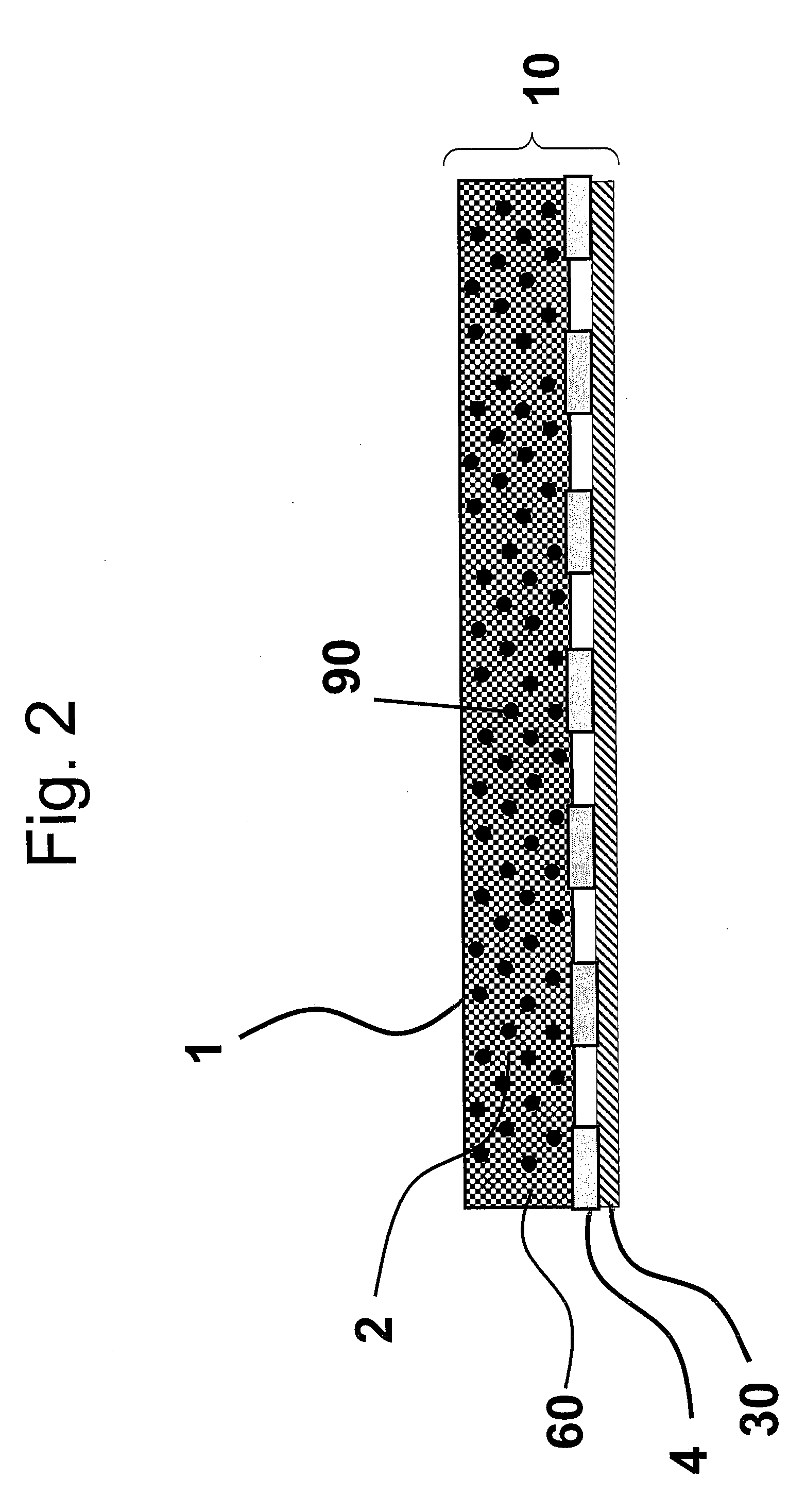
[0089]A sample of a construct was prepared comprising a layer of carbon-coated ePTFE, Al foil, and a textile backer as follows.
[0090]A first component of carbon-coated ePTFE was prepared as described in Example 1, representing the first substrate. Optical density and thermal transmission properties of the first substrate were measured according to the test methods herein, and reported in Table 1.
[0091]A second component was prepared comprising a discontinuous layer of foil adhered to a textile backer, representing the thermally reflective layer. The second component was formed by perforating a layer of Al transfer foil from Crown Roll Leaf, Inc (part #MG39-100 G) to provide approximately 30% open area to form a discontinuous layer of transfer foil. The discontinuous layer of transfer foil was adhered to a textile backer using a continuous thermoplastic polyurethane adhesive (8) to form the second component, representing the thermally reflective layer. The layers were bonded together...
example 3
[0093]A sample of a construct was prepared comprising a layer of colored ePTFE, Al foil and a textile backer as follows.
[0094]A first component was prepared by coloring a layer of 1.2 mil ePTFE (about 0.2 micron average pore size, and about 18 grams per square meter) with a single substantially continuous coating of black Sharpie® permanent marker to comprise the first substrate of the construct. Optical density and thermal transmission properties of the first substrate were measured according to the test methods herein, and reported in Table 1.
[0095]A second component was prepared by perforating a layer of Al transfer foil from Crown Roll Leaf, Inc (part #MG39-100 G) to provide approximately 30% open area to form a discontinuous layer of transfer foil to comprise the thermally reflective layer. This discontinuous layer of transfer foil was adhered to a textile backer using a continuous thermoplastic polyurethane adhesive. The foil and textile backer layers were bonded together usin...
PUM
| Property | Measurement | Unit |
|---|---|---|
| emissivity | aaaaa | aaaaa |
| thickness | aaaaa | aaaaa |
| thickness | aaaaa | aaaaa |
Abstract
Description
Claims
Application Information