Sensor for observations in liquid environments and observation apparatus for use in liquid environments

a technology for observation apparatus and liquid environments, applied in the direction of mechanical measurement arrangements, mechanical roughness/irregularity measurements, instruments, etc., can solve the problems of difficult work, high labor and time requirements, and difficult prealignment, etc., to achieve enhanced operability, simple method utilizing, and convenient use

Inactive Publication Date: 2009-10-22
HITACHI HIGH TECH SCI CORP
View PDF2 Cites 14 Cited by
  • Summary
  • Abstract
  • Description
  • Claims
  • Application Information

AI Technical Summary

Benefits of technology

[0047]In the observation apparatus associated with the invention and adapted for observations under liquid environments, suction is performed via the suction passages after the sensor for observations under liquid environments is placed on the cantilever holder. Consequently, the sensor can be attracted and held on the cantilever holder. In this way, the sensor for observations under liquid environments can be set on the cantilever holder by a simple method utilizing an attractive force.
[0048]The inventive sensor for observations in liquid environments makes it possible to make observations of a sample in a liquid by making use of a self-detecting probe without being affected by the liquid at all.
[0049]The inventive observation apparatus adapted for observ

Problems solved by technology

However, the prealignment is a very difficult work to perform because the optical path is aligned relative to the cantilever having a diameter of as small as tens of micrometers.
Consequently, much labor and time are required.
Especially, where observations are made under liquid environments, the cantilever is submerged in a liquid, making the work difficult.
Unfortunately, this work itself is difficult for a novice to perform.
For this reason, the present situation is that when the cantilever is mounted, the cantilever is damaged frequently.
Consequently, very cumbersome preparative steps must be carried out until an observation or measurement is started in practice.
In particular, the development of the self-detecting probe 100 can dispense with the work for aligning the laser light, which has been heretofore difficult

Method used


Image

  • Sensor for observations in liquid environments and observation apparatus for use in liquid environments
  • Sensor for observations in liquid environments and observation apparatus for use in liquid environments
  • Sensor for observations in liquid environments and observation apparatus for use in liquid environments

Examples


first embodiment

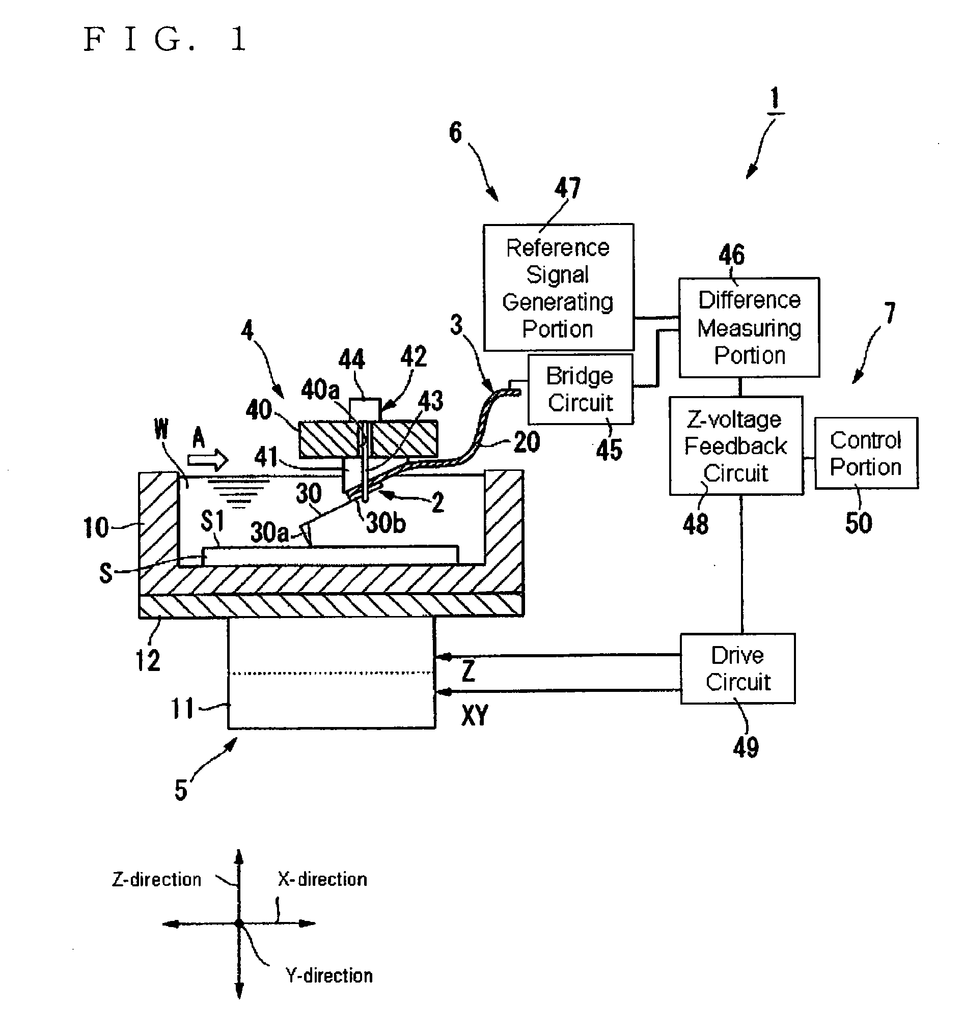
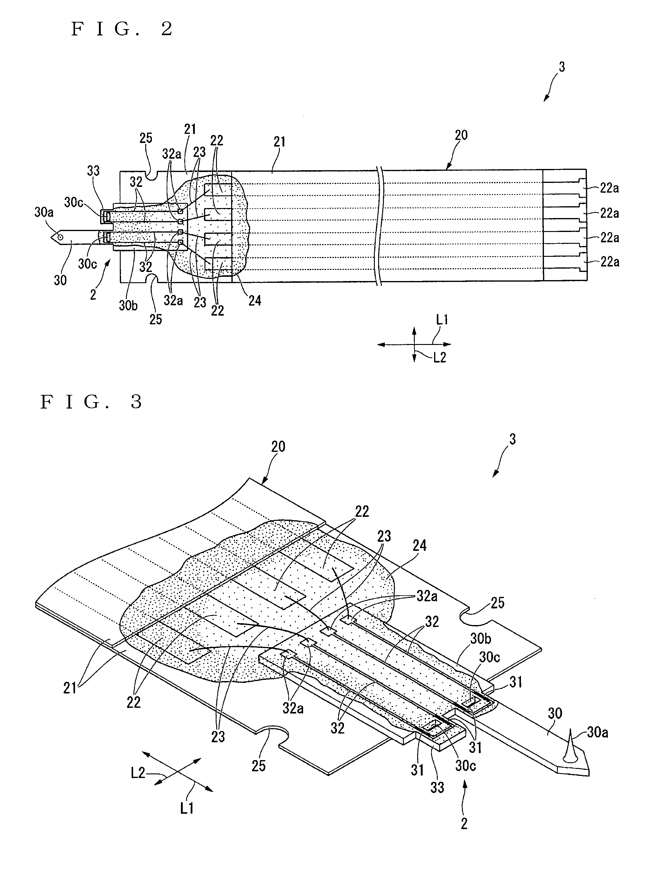
[0073]A first embodiment associated with the present invention is hereinafter described with reference to FIGS. 1-5. In the present embodiment, an example is given in which measurements are made after a sample S has been entered in a liquid vessel 10 where a liquid W is stored. An observation apparatus 1 of the present embodiment is used to observe the sample S in the liquid by measuring the topography of the surface of the sample S within the liquid W or various physical properties such as viscoelasticity. As shown in FIG. 1, the apparatus 1 has a sensor 3 for observations under liquid environments, a cantilever holder 4, a moving mechanism 5, a detection mechanism 6, and an observation mechanism 7. The sensor 3 has a self-detecting probe 2.

[0074]First, the sample S is held to the bottom surface of the liquid vessel 10 to prevent the sample from moving. The vessel 10 has an open top portion of U-shaped cross section. The vessel 10 is held on a sample stage 12, which in turn is fixe...

second embodiment

[0110]A second embodiment associated with the present invention is next described by referring to FIGS. 6-8. In the second embodiment, those components which are identical with their counterparts of the first embodiment are indicated by the same reference numerals as in the first embodiment and their description will be omitted.

[0111]The difference between the second and first embodiments is as follows. In the first embodiment, the sensor 3 for observations under liquid environments is held using the wires 43. In the second embodiment, the sensor 3 is held using fixing pins 63.

[0112]An observation apparatus of the present embodiment is adapted for observations under liquid environments and generally indicated by reference numeral 60. As shown in FIG. 6, the apparatus 60 has a fixing mechanism 62 having the fixing pins 63 of one pair. As shown in FIGS. 7(a) and (b), the fixing pins 63 are inserted in slots 40b extending through the holder body 40. The pins 63 can move in the widthwis...

third embodiment

[0118]A third embodiment associated with the present invention is next described by referring to FIGS. 9-12. In the third embodiment, those components which are identical with their counterparts of the first embodiment are indicated by the same reference numerals as in the first embodiment and their description will be omitted.

[0119]The differences between the third and first embodiments are as follows. In the first embodiment, the sensor 3 for observations in liquid environments is held by making use of the wires 43. In the third embodiment, the sensor 3 is held by utilizing fixing pins 73. In the first embodiment, the self-detecting probe 2 is supported to one end of the flexible substrate 20, while the external contacts 22a are formed on the other end. In the third embodiment, the self-detecting probe 2 is supported to around the center of the flexible substrate 20. The external connects 22a are formed at both ends.

[0120]That is, an observation apparatus of the present embodiment...


PUM


Abstract

The sensor has the self-detecting probe including a body portion, an elongated belt-like flexible substrate, connecting members, a resinous portion, and external contacts formed at the ends of the flexible substrate brought out of liquid. The probe further includes a cantilever whose base end is supported to the body portion, a strain resistive element whose resistance value varies according to the amount of displacement of the cantilever, and interconnects electrically connected with the strain resistive element. A probe tip is formed at the front end of the cantilever. The flexible substrate has an interconnect pattern sandwiched between two insulating sheets. The flexible substrate supports the body portion while the cantilever protrudes outwardly. At least one end of the flexible substrate is brought out of liquid. The connecting members connect the interconnects with the interconnect pattern. The interconnects, connecting members, and the portions of the connecting members electrically connected with the interconnect pattern are coated with the resinous portion.

Description

RELATED APPLICATIONS[0001]This application claims priority under 35 U.S.C. §119 to Japanese Patent Application No. JP2008-106897 filed on Apr. 16, 2008, the entire content of which is hereby incorporated by reference.BACKGROUND OF THE INVENTION[0002]1. Field of the Invention[0003]The present invention relates to a sensor used for observations of the topography of sample surfaces and various physical properties (such as viscoelasticity) under liquid environments by making use of a self-detecting probe. The invention also relates to an observation apparatus for use in liquid environments.[0004]2. Description of the Related Art[0005]In recent years, with development of the nanotechnology, techniques for imaging and observing the surfaces of samples such as bio samples and semiconductor samples at high resolution have been required. One known apparatus for realizing this requirement is a scanning probe microscope (SPM). The scanning probe microscope is an instrument capable of imaging v...

Claims


Application Information

Patent Timeline
IPC IPC(8): G01N13/10G01Q60/00
CPCB82Y35/00G01Q30/14G01Q20/04
Inventor WATANABE, NAOYASHIGENO, MASATSUGUIYOKI, MASATO
Owner HITACHI HIGH TECH SCI CORP
Why Eureka
Try Eureka