Work positioning method, and positioning device

a positioning device and work technology, applied in the field of work positioning methods, can solve the problems of long lead time, inability to accurately machine-process work, and cost and detection time, and achieve the effects of enhancing the positioning accuracy, and improving the accuracy of the positioning devi

Active Publication Date: 2009-10-29
TOYOTA JIDOSHA KK +1
View PDF18 Cites 17 Cited by
  • Summary
  • Abstract
  • Description
  • Claims
  • Application Information

AI Technical Summary

Benefits of technology

[0084]The invention described in (9) is the work positioning device having the same configuration as in (2). Thus, the auxiliary positioning means can be additionally provided with the inner-diameter holding function with respect to the auxiliary positioning hole. The main positioning means and the auxiliary positioning means are additionally provided with the inner-diameter holding function with respect to respective positioning holes, so that positioning accurac

Problems solved by technology

In an automatic machining process of a work, if a reference point of the work to be processed is not accurately grasped relative to an origin point of a machine tool, the work could not be accurately machine-processed.
However, it requires costs and detection time, resulting in a long lead time.
It is ideal to provide a machining line per kind of work; however, it does not worth the cost for a small number of lots, and therefore one line is sometimes used for processing a plurality of kinds of works.
However, the techniques disclosed in Patent Literatures 1 to 4 may have a problem with difficulty in improving the positioning a

Method used


Image

  • Work positioning method, and positioning device
  • Work positioning method, and positioning device
  • Work positioning method, and positioning device

Examples


first embodiment

[0164]Firstly, the configuration of a first embodiment will be explained.

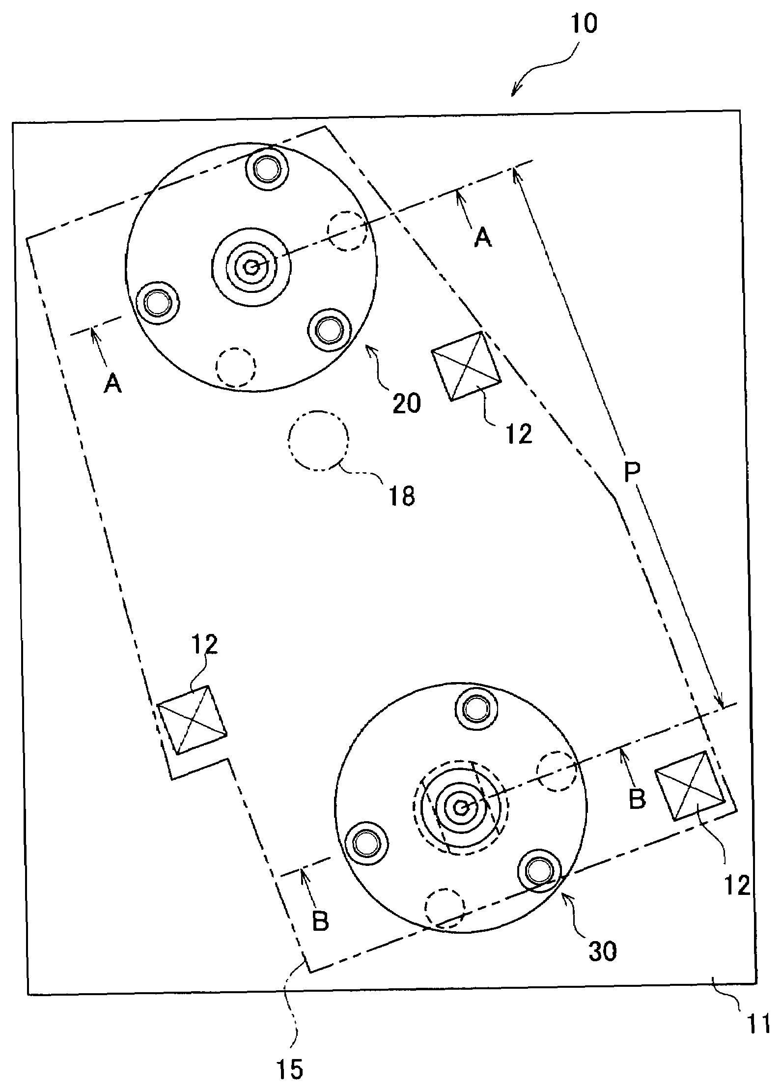
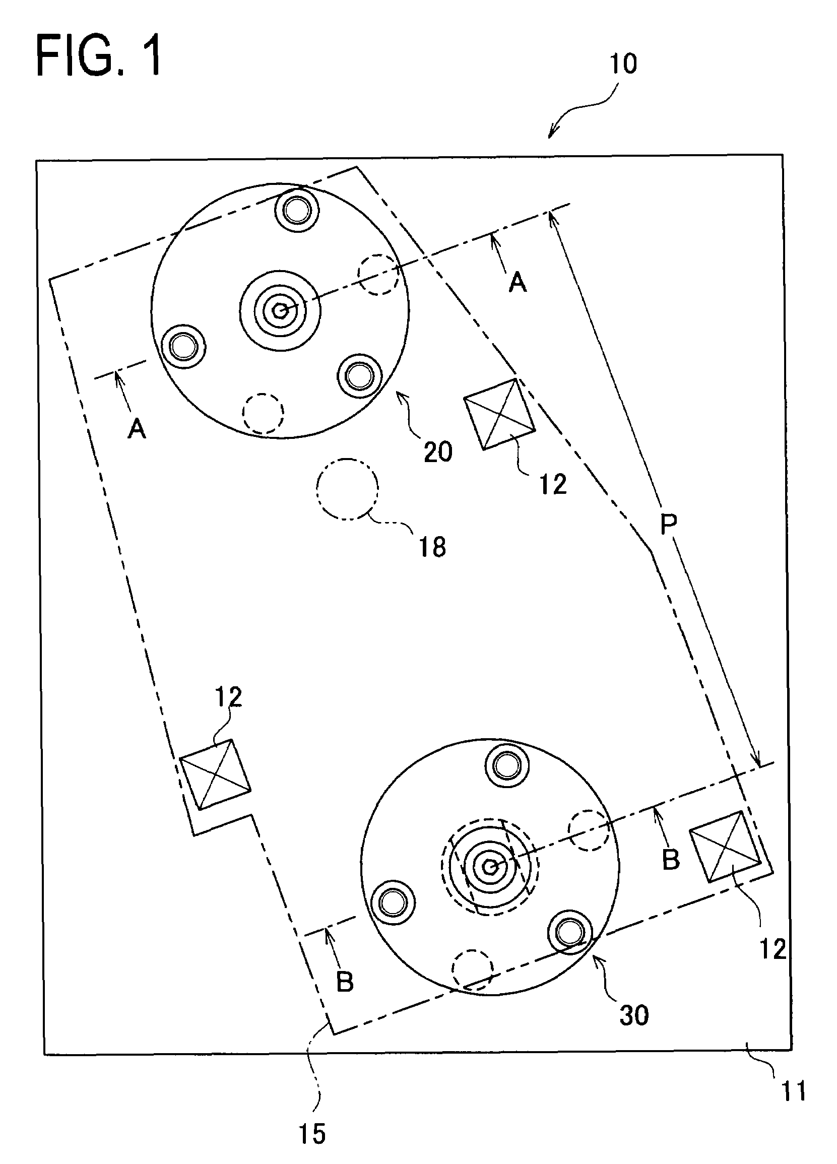
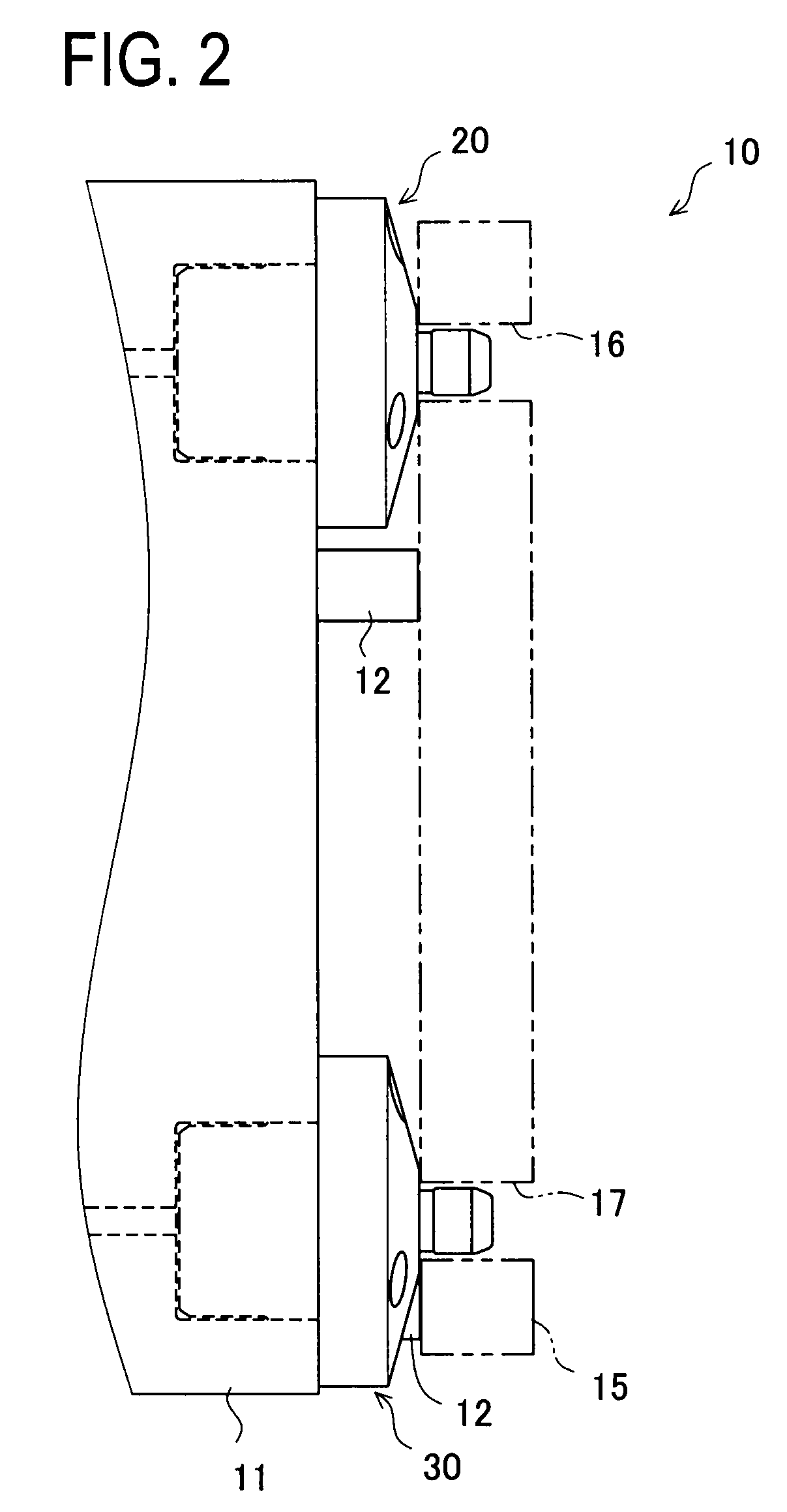
[0165]FIG. 1 is a top view of a positioning device 10 in the first embodiment. FIG. 2 is a side view of the positioning device 10. The positioning device 10 includes a reference block 11, reference seats 12, a main positioning unit20, and an auxiliary positioning unit 30 and is arranged to perform positioning of a work 15.

[0166]The main positioning unit 20 and the auxiliary positioning unit 30 are secured to the reference block 11 with bolts.

[0167]The reference block 11 is a block that has a reference plane 11a shown in FIG. 3 and other figures mentioned later and is formed with a plurality of oil feed passages such as a first oil feed passage 11b and a second oil feed passage 11c. These oil feed passages are coupled to an oil pump or the like so as to be supplied with pressurized oil.

[0168]Furthermore, an air supply passage may be formed to supply compressed air as needed. Air supplied through this air supply ...

second embodiment

[0232]Next, the configuration of a second embodiment will be described.

[0233]A positioning device 10 in the second embodiment has the same configuration as that in the first embodiment, except that the internal structures of the main positioning unit 20 and the auxiliary positioning unit 30 are different from those of the positioning unit 10 in the first embodiment.

[0234]Therefore, the following explanation is given to the main positioning unit 20 and the auxiliary positioning unit 30. The main positioning unit 20 is first explained.

[0235]FIG. 9A is a top view of the main positioning unit 20 in the second embodiment. FIG. 9B is a sectional view of the main positioning unit 20 corresponding to a view taken along the line A-A in FIG. 1.

[0236]The main positioning unit 20 includes an insert cap member A21, inner-diameter holding balls A22, a base block A24, a piston A25, a tapered shaft A27, and others. Of them, the insert cap member A21 corresponds to the main positioning insertion par...

third embodiment

[0284]Next, the configuration of a third embodiment will be described.

[0285]A positioning device 10 in the third embodiment has the same configuration as that in the second embodiment, except for the auxiliary positioning unit 30. Specifically, the third embodiment shows a modified example of the auxiliary positioning unit 30 of the second embodiment. Thus, the configuration of the auxiliary positioning unit 30 is explained.

[0286]FIG. 11A is a sectional view of the auxiliary positioning unit 30 of the third embodiment, taken along a line G-G in FIG. 11B. FIG. 11B is a sectional view of the auxiliary positioning unit 30 corresponding to a view taken along the line B-B in FIG. 1.

[0287]The auxiliary positioning unit 30 includes an insert cap member B31, inner-diameter holding balls B32, a base upper block B35, a base lower block B36, a piston B37, and others.

[0288]The insert cap member B31 corresponds to the insert cap member A31 and is formed in a cylindrical shape internally having a...


PUM

PropertyMeasurementUnit
Diameteraaaaaaaaaa

Abstract

Intended is to provide a method for positioning a work (15), which is adapted for a knock hole of a small diameter and which can absorb a pitch error between a main positioning hole (16) and an auxiliary positioning hole (17) of the work (15). An insert shaft (21) of main positioning means 820) is inserted into the main positioning hole (16). Auxiliary positioning means (30) includes a base lower block (36) having a parallel slide holding surface (36e), a sliding flange (34b) having a sliding surface (34c), and an insert shaft (31) disposed above the sliding flange (34b). The sliding flange (34b) of the auxiliary positioning means (30) is guided and moved by the slide holding surface (36e), and is inserted, while absorbing the pitch error, into the auxiliary positioning hole (17), thereby to position the work (15).

Description

CROSS-REFERENCE TO RELATED APPLICATIONS[0001]This is a national phase application filed under 35 U.S.C 371 of PCT / JP2008 / 061372 filed on Jun. 16, 2008, which claims the benefit of priority from the prior Japanese Patent Application No. 2007-160945 filed on Jun. 19, 2007, the entire contents of all of which are incorporated herein by reference.TECHNICAL FIELD[0002]The present invention relates to a technique of positioning a work or workpiece and more particularly to a technique of accurately positioning a work by absorbing a machining error of a positioning hole formed in the work.BACKGROUND ART[0003]For machining process, machine assembling, etc., it is very important to position a work or workpiece which will be processed or assembled.[0004]In an automatic machining process of a work, if a reference point of the work to be processed is not accurately grasped relative to an origin point of a machine tool, the work could not be accurately machine-processed. In automatic machine asse...

Claims


Application Information

Patent Timeline
IPC IPC(8): B23Q3/00B23Q7/00
CPCB23Q1/009Y10T29/49998B23Q3/183B23Q3/00B23Q3/06B23Q3/18
Inventor KITAMURA, TAKAHIROSUGIURA, KOICHIKAWAKAMI, TAKAYUKIKURODA, TAKAYUKI
Owner TOYOTA JIDOSHA KK
Why Eureka
Try Eureka