
High-voltage bus discharge with logarithmic self-protection

a high-voltage bus and self-protection technology, applied in the direction of electric devices, process and machine control, instruments, etc., can solve the problems of overheating and destroying the discharge resistor, constant voltage across the capacitor terminal, and power consumption of the various electrical systems of the automobil

Active Publication Date: 2009-10-29
GM GLOBAL TECH OPERATIONS LLC
View PDF10 Cites 36 Cited by
  • Summary
  • Abstract
  • Description
  • Claims
  • Application Information

AI Technical Summary

Benefits of technology

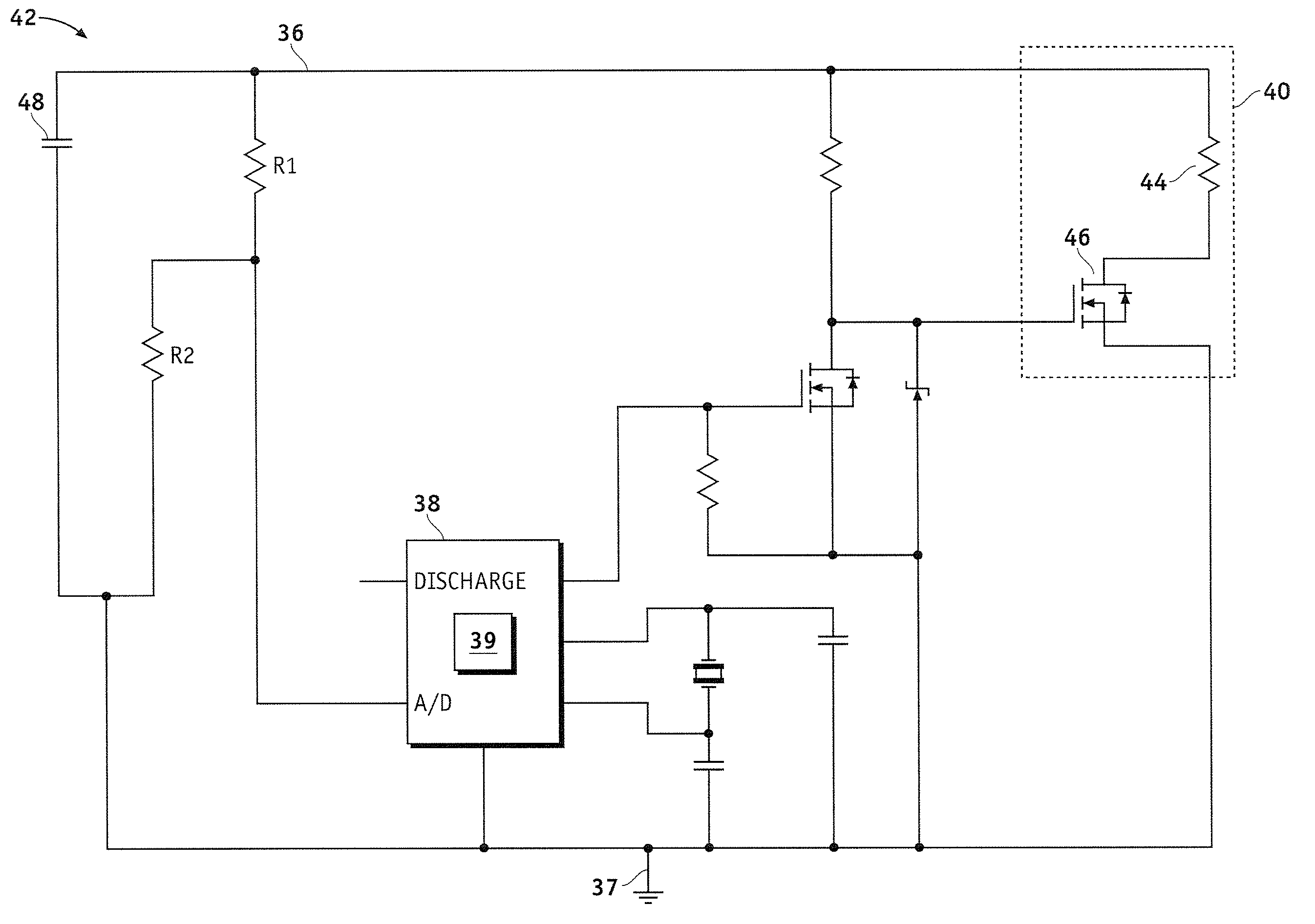
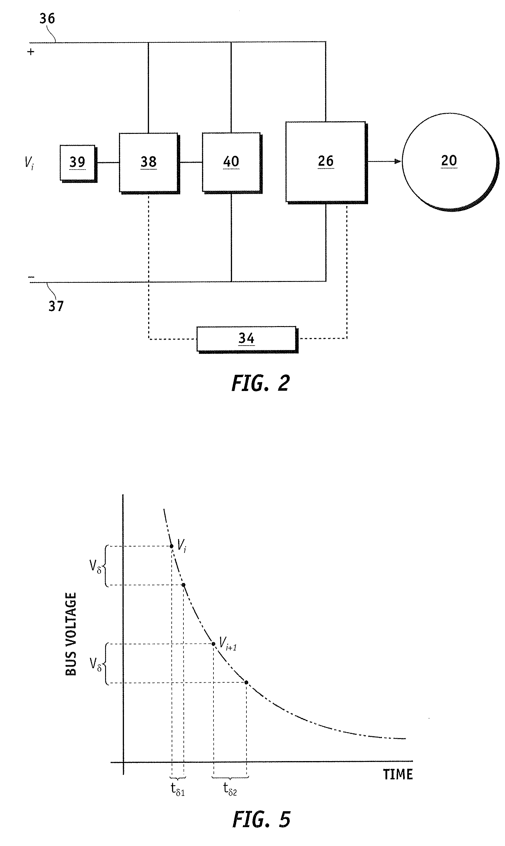
[0007]A method is provided for controlling a discharge circuit coupled to a high-voltage bus, wherein the discharge circuit is activated such that current flows from the high-voltage bus through the discharge circuit. The method comprises determining a first discharge time based on a first voltage level of the high-voltage bus, obtaining a second voltage level of the high-voltage bus after the first discharge time, and deactivating the discharge circuit if a difference between the first voltage level and the second voltage level is less than a threshold value.
[0008]A method is provided for discharging a high-voltage bus coupled to a discharge circuit. The method comprises obtaining a first voltage level of the high-voltage bus. The method further comprises determining a first discharge time based on the first voltage level and activating the discharge circuit. The method further comprises obtaining a second voltage level of the high-voltage bus after the first discharge time, comparing the first voltage level and the second voltage level, and deactivating the discharge circuit if a difference between the first voltage level and the second voltage level is less

Problems solved by technology

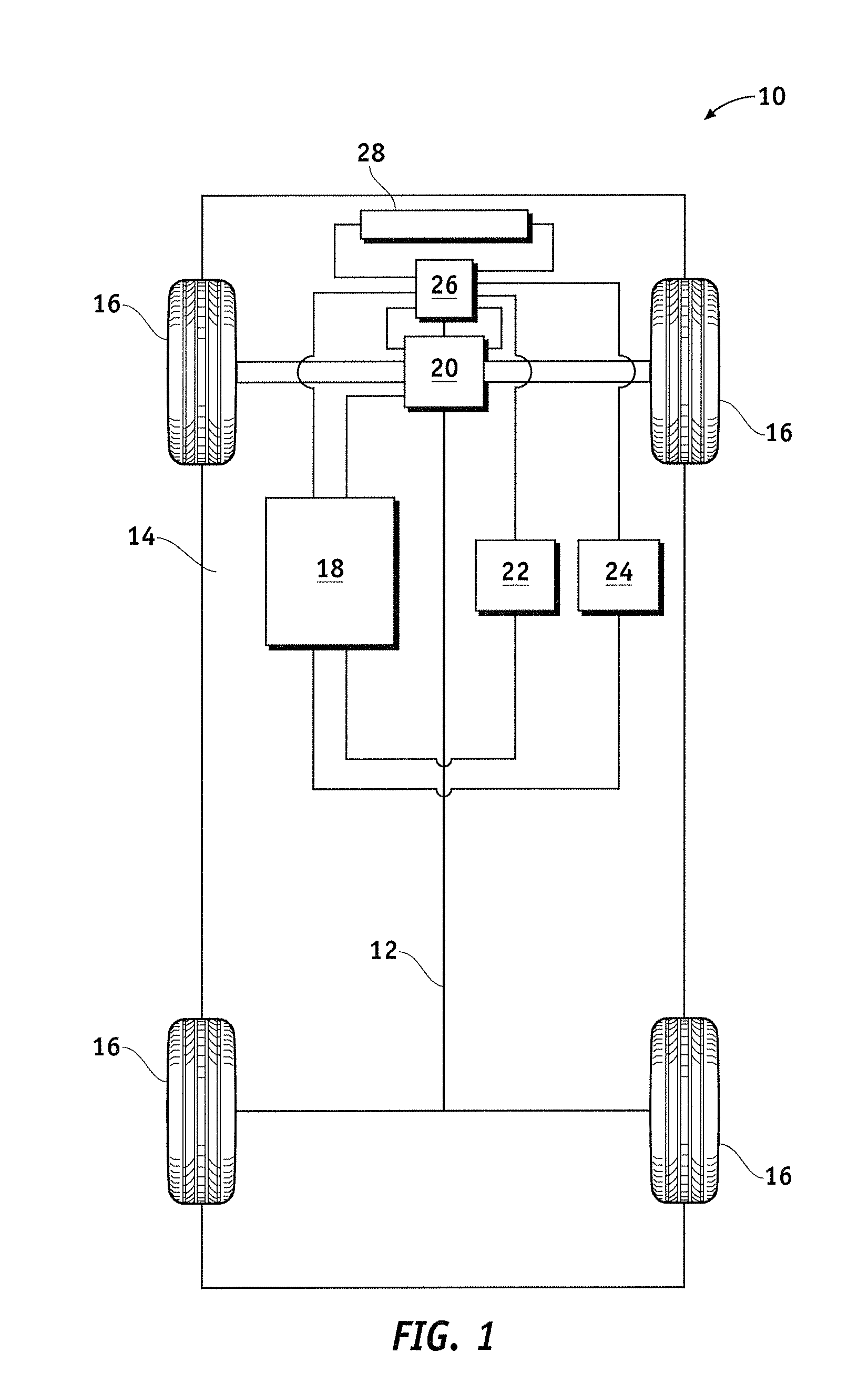
One of the changes involves the power usage and complexity of the various electrical systems within automobiles, particularly alternative fuel vehicles, such as hybrid, electric, and fuel cell vehicles.
However, capacitors may retain a charge long after power is removed from a circuit or an automobile is turned off.
In an automobile, there are possible fault conditions that may result in a constant voltage across the capacitor terminals.
If a fault is not properly detected and protected against, attempting to discharge the capacitor will overheat and destroy the discharge resistor.
Moreover, the failure of a discharge resistor prevents future discharge, resulting in voltage being retained on a capacitor or within the circuit for an extended period of time.
Previous discharge circuits and methods require unacceptably high average power dissipation in a discharge resistor during fault conditions and are not easily adaptable to higher voltage levels.
These resistors generally occupy a larger surface area and often require additional harnesses, connectors, and heat sinks, which prevent the discharge resistors from being built on a circuit board.

Method used


Image

  • High-voltage bus discharge with logarithmic self-protection
  • High-voltage bus discharge with logarithmic self-protection
  • High-voltage bus discharge with logarithmic self-protection

Examples


Embodiment Construction

[0017]The following detailed description is merely illustrative in nature and is not intended to limit the embodiments of the subject matter or the application and uses of such embodiments. Although the embodiments of the subject matter are discussed herein in the context of vehicle drive systems, the subject matter may apply to alternative implementations in other applications. As used herein, the word “exemplary” means “serving as an example, instance, or illustration.” Any implementation described herein as exemplary is not necessarily to be construed as preferred or advantageous over other implementations. Furthermore, there is no intention to be bound by any expressed or implied theory presented in the preceding technical field, background, brief summary or the following detailed description.

[0018]The following description refers to elements or nodes or features being “connected” or “coupled” together. As used herein, unless expressly stated otherwise, “connected” means that on...


PUM


Abstract

Systems and methods for discharging a high-voltage bus coupled to a discharge circuit are provided. A method comprises obtaining a first voltage level of the high-voltage bus. The method further comprises determining a first discharge time based on the first voltage level and activating the discharge circuit. The method further comprises obtaining a second voltage level of the high-voltage bus after the first discharge time, comparing the first voltage level and the second voltage level, and deactivating the discharge circuit if a difference between the first voltage level and the second voltage level is less than a threshold value.

Description

TECHNICAL FIELD[0001]Embodiments of the subject matter described herein relate generally to electric and hybrid vehicle drive systems, and more particularly, embodiments of the subject matter relate to discharge circuits for high-voltage bus capacitance.BACKGROUND[0002]In recent years, advances in technology, as well as ever evolving tastes in style, have led to substantial changes in the design of automobiles. One of the changes involves the power usage and complexity of the various electrical systems within automobiles, particularly alternative fuel vehicles, such as hybrid, electric, and fuel cell vehicles.[0003]In most hybrid vehicles, energy storage devices, such as capacitors, are often used to improve efficiency by capturing energy within the powertrain system or supplying additional power during periods of operation when a primary energy source cannot supply the required power quickly enough. For example, regenerative braking may be used to capture energy by converting kinet...

Claims


Application Information

Patent Timeline
IPC IPC(8): H02H3/24H02H7/16H02J7/00
CPCB60L3/0023B60L2240/70B60L2200/26Y02T10/7291Y02T90/16H02H3/14Y02T10/72
Inventor KAPLAN, DANIEL J.
Owner GM GLOBAL TECH OPERATIONS LLC
Learn More