Temperature sensor element and method of manufacturing the same

a technology of temperature sensor and manufacturing method, which is applied in the direction of instruments, heat measurement, transportation and packaging, etc., can solve the problems of limiting the improvement of responsiveness, affecting the effect of output, and the responsiveness of the time of temperature detection, so as to improve the thermal conductivity between the sintered body and the thermocouple, improve the adhesion, and improve the effect of adhesion

Inactive Publication Date: 2009-10-29
NGK SPARK PLUG CO LTD
View PDF3 Cites 28 Cited by
  • Summary
  • Abstract
  • Description
  • Claims
  • Application Information

AI Technical Summary

Benefits of technology

[0010]A technique for improving the thermal conductivity from the protective tube to the sensitive member using a filler (insulating powders, cement or the like) filled therebetween has been proposed (Patent Documents 1 and 3). However, such a temperature sensor element has the sensitive member whose circumference is covered by two members (a protective tube and a filler). Considering allocation area of these two members, a reduction in a physical distance from the sensitive member to the measurement gas is limited, thereby limiting an improvement in the responsiveness.
[0041]Therefore, according to the method of the present invention, it is possible to produce the temperature sensor element excellent in durability as well as having good responsiveness at the time of temperature detection.

Problems solved by technology

However, the conventional temperature sensor element having a structure where a sensitive member is accommodated in a protective tube tends to have a problem that responsiveness at the time of temperature detection is likely to deteriorate.
This problem is caused by an air layer formed between the sensitive member and the protective tube, or a delay of thermal conduction due to heat capacity of the protective tube or the like.
Considering allocation area of these two members, a reduction in a physical distance from the sensitive member to the measurement gas is limited, thereby limiting an improvement in the responsiveness.
However, the temperature sensor element having the exposed sensitive member tends to cause a variation of output due to material deterioration (i.e., a soot adhesion to the sensitive member or corrosion thereof or the like).
As a result, durability of the temperature sensor element tends to be a problem.

Method used


Image

  • Temperature sensor element and method of manufacturing the same
  • Temperature sensor element and method of manufacturing the same
  • Temperature sensor element and method of manufacturing the same

Examples


Embodiment Construction

[0045]The embodiment of the present invention will be described with reference to the drawings.

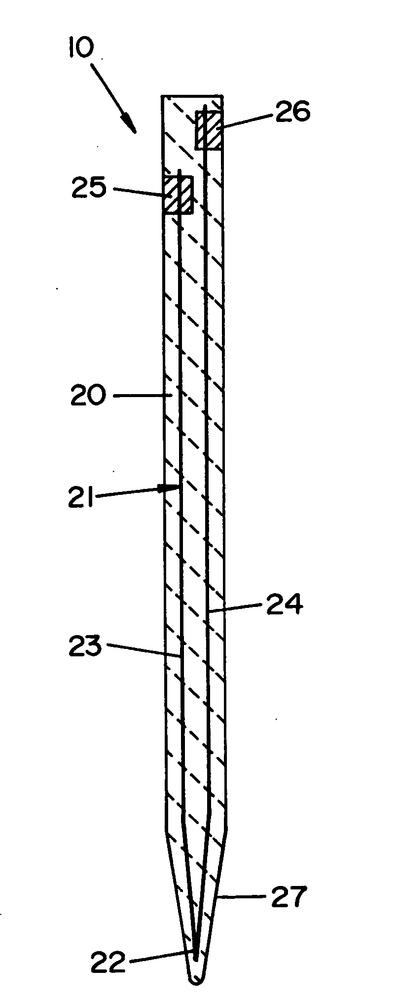
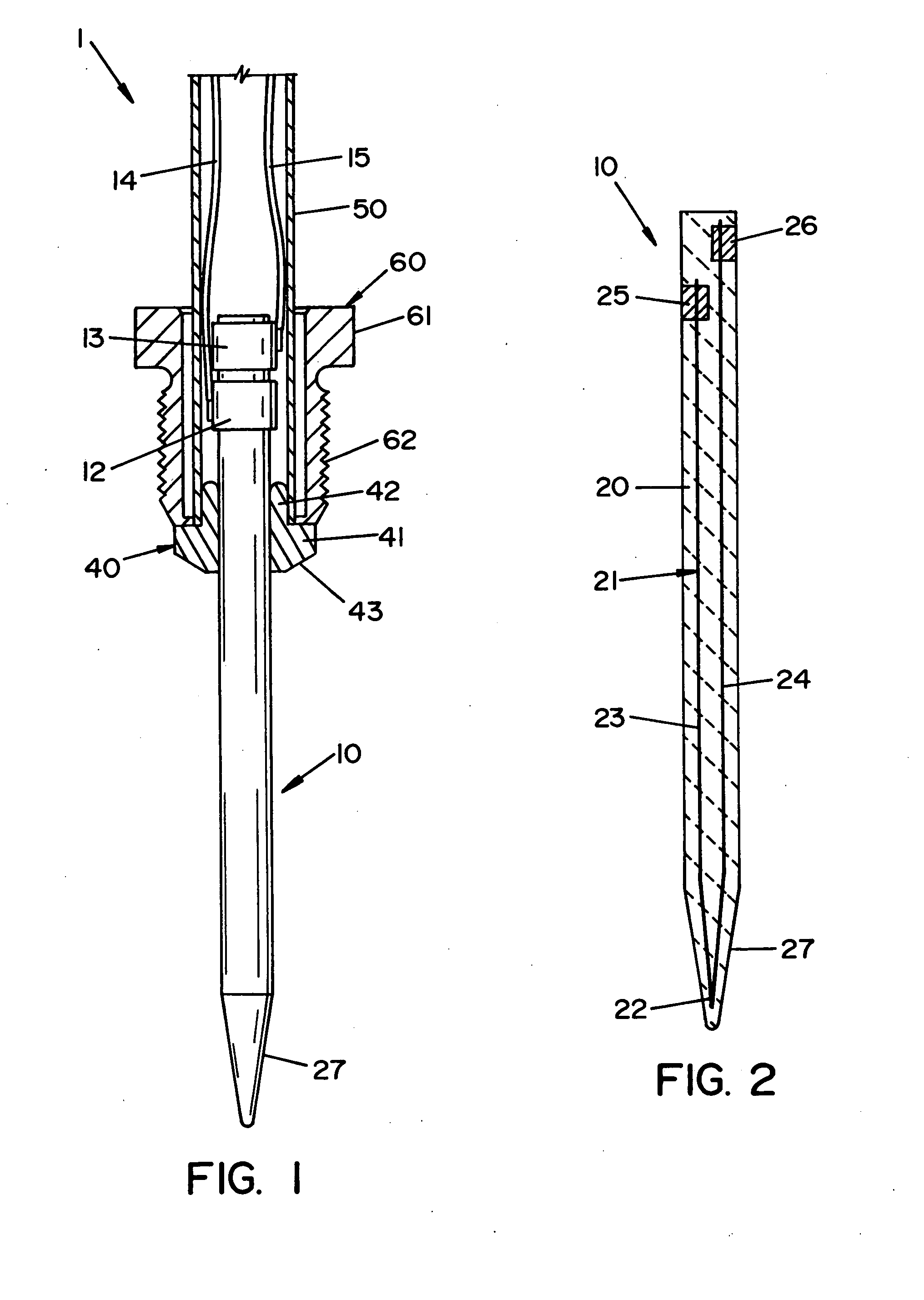
[0046]First, a partially sectional view of a temperature sensor 1 having a temperature sensor element 10 according to an embodiment of the present invention is shown in FIG. 1.

[0047]It is noted that the temperature sensor 1 is used for a temperature detection of an exhaust gas. The temperature sensor 1 is located at both front and rear sides of an exhaust port of an automobile, particularly, an exhaust gas after treatment device of a diesel engine. A front end portion of the temperature sensor element 10 is disposed in the exhaust port where an exhaust gas flows.

[0048]As shown in FIG. 1, the temperature sensor 1 is comprised of the temperature sensor element 10, a flange member 40, a joint member 50 and a nut member 60.

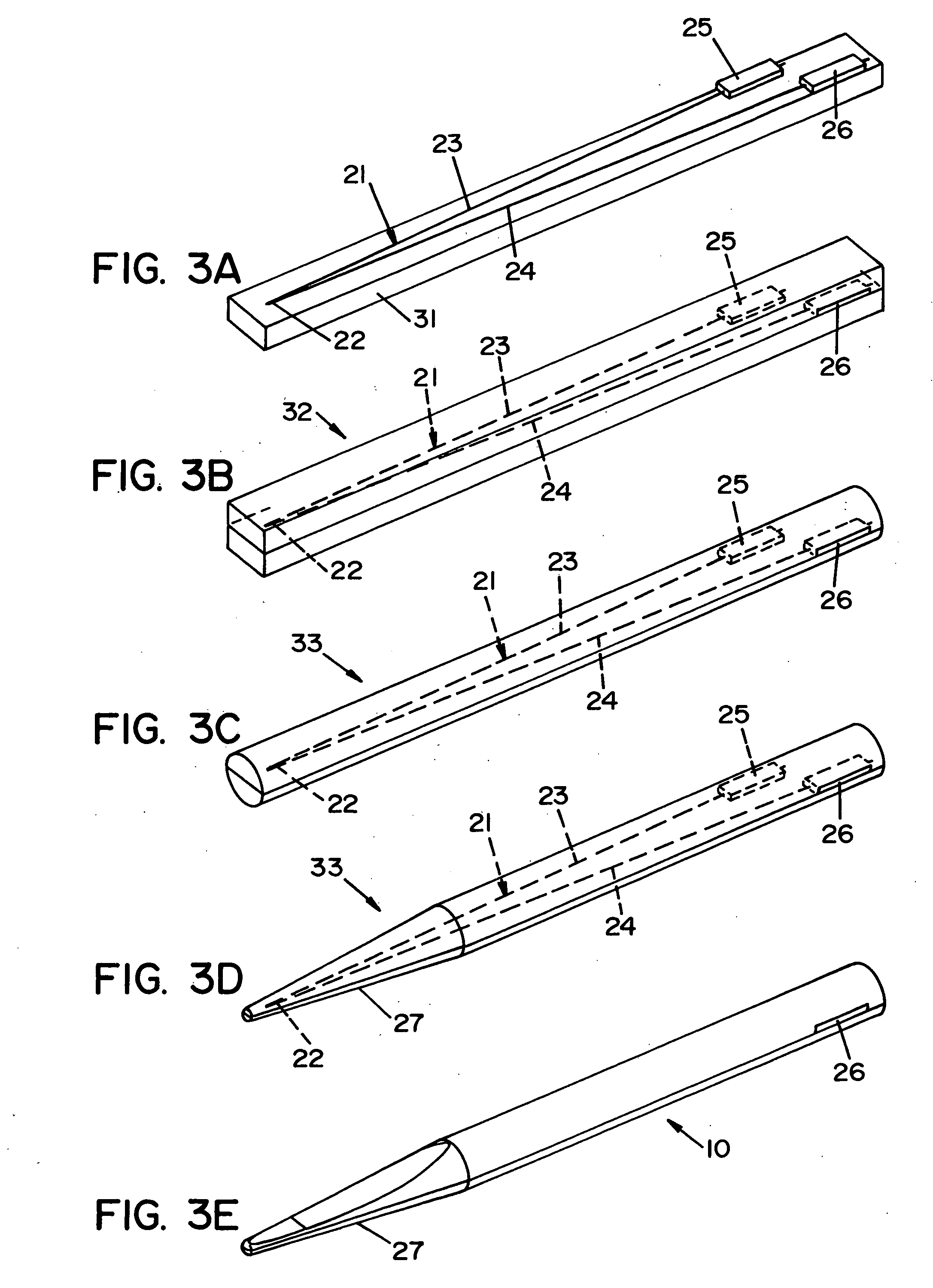
[0049]The lengthy temperature sensor element 10 extends in an axial direction and has therein a thermocouple 21 (refer to FIG. 2) for detecting a temperature. Further, the f...


PUM

PropertyMeasurementUnit
porosityaaaaaaaaaa
porosityaaaaaaaaaa
temperatureaaaaaaaaaa

Abstract

A temperature sensor element 10 has a reduced thermal conduction path from a measurement object to a sensitive end portion 22 of a thermocouple 21 and a high-dense insulating ceramic base body 20. Since the temperature sensor element 10 has excellent thermal conductivity from the measurement object to the sensitive end portion 22 of the thermocouple 21, it is also excellent in responsiveness at the time of temperature detection. Further, corrosion and material deterioration of the thermocouple 21 is unlikely to occur because the thermocouple 21 does not directly contact the measurement object (exhaust gas). As a result, the temperature sensor element 10 exhibits excellent durability. Therefore, the temperature sensor element 10 exhibits a good responsiveness at the time of temperature detection as well as excellent durability.

Description

BACKGROUND OF THE INVENTION[0001]The present invention relates to a method for manufacturing a temperature sensor element comprised of a lengthy sintered body which extends in an axial direction and is made of insulating ceramic, a sensitive member embedded in the sintered body and a signal output portion for outputting an electric signal received from the sensitive member to the outside.[0002]Conventionally, it has been known that a temperature sensor element has a structure in which a sensitive member is accommodated in a protective tube, such as a metal sheath, a case and a metal tube (see Patent Documents 1, 2 and 3). Such a temperature sensor element detects temperature in such a manner that the temperature of a measurement object conducts and reaches to a sensitive member through the protective tube.[0003]Further, another disclosed temperature sensor element has a structure in which an electrically conductive layer used as the sensitive member is exposed (see Patent Document 4...

Claims


Application Information

Patent Timeline
Patent Type & Authority Applications(United States)
IPC IPC(8): G01K7/02
CPCG01K1/10G01K2205/04G01K7/04G01K1/18
Inventor HOTTA, NOBUYUKIOHBAYASHI, KAZUSHIGE
Owner NGK SPARK PLUG CO LTD
Why Eureka
Try Eureka